Hi Sirs,
Sorry to bother you.
After study Ref board, we have two question.
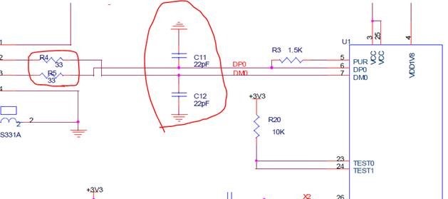
1. Why need to add R and C on D+ and D-? what is the R and C function?
2. On power Pin, are there any suggested placement and recommended Cap value for Layout design?
This thread has been locked.
If you have a related question, please click the "Ask a related question" button in the top right corner. The newly created question will be automatically linked to this question.
Hi Sirs,
Sorry to bother you.
After study Ref board, we have two question.
1. Why need to add R and C on D+ and D-? what is the R and C function?
2. On power Pin, are there any suggested placement and recommended Cap value for Layout design?
Hello,
First, R4 and R5 serve to help with ESD, and dissipate enough power for the internal ESD diodes in the 3410 to take care of the rest. The capacitors are used for edge rate control.
Section 6.2.2.4 in the datasheet gives you recommended capacitor values of TUSB3410. The placement, as with most capacitances on power should be as close as possible to the power pins of the device.
Best,
Gerasimos