Hi,
My question has below question for retimer DS11DF410, Can help to check and give some suggestion? Thanks a lot.
- The Retimer chip has 25M refclk output. How is the clock generated inside the chip? Is it the recovered from CDR? Can it be used as the recover clock of syncE.
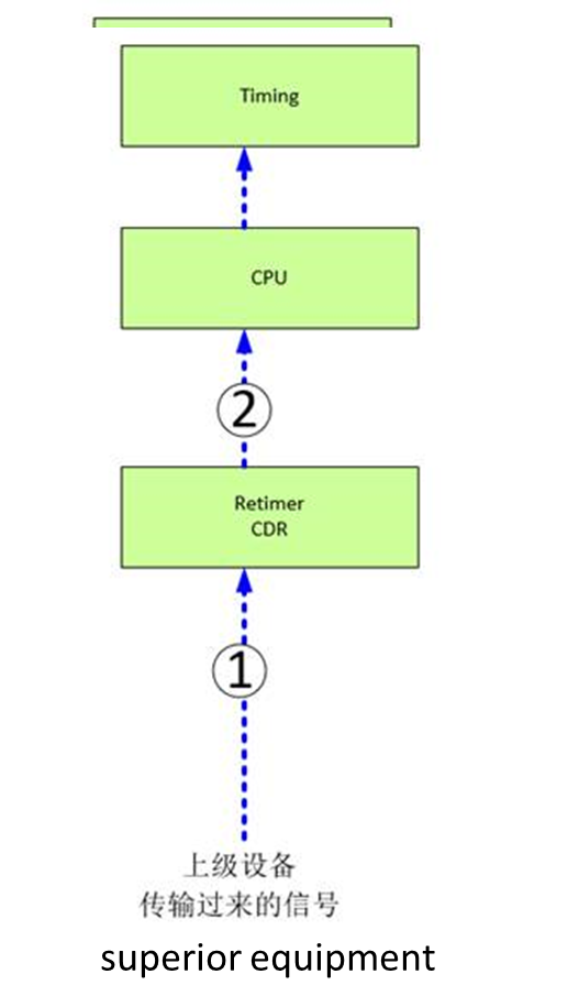
- shown in the diagram below, the superior equipment sending signals to the Retimer, Retimer inside will have the CDR, and recover the clock, then then send it to the CPU, could you tell me the difference between the clock in position-1(before the retimer ) and the clock in position-2 (after the retimer). (Will the clock and PTP information be out of alignment with the upper level equipment with delay, frequency deviation, etc?). Is there anything wrong with syncE clock that CPU recovered from position 2? Is it necessary for the CPU to access the CDR in the retimer through I2C? CPU reads some adjustment parameters in the CDR to adjust the clock from the retimer to achieve the synchronization with the clock in position 1?