A related question is a question created from another question. When the related question is created, it will be automatically linked to the original question.
If you have a related question, please click the "Ask a related question" button in the top right corner. The newly created question will be automatically linked to this question.
When VDDO_x is 3.3V, the internal LDO regulator limits the swing of LVCMOS to about 2.8V ± 0.1V. We do not characterize the 3.3V LVCMOS output case, so consider my number a typical value only. These numbers are not a guarantee.
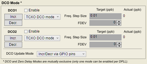
DCO mode is completely documented in the datasheet section 9.4.4, please reference this. You adjust the phase by adjusting the target PLL output frequency until the desired phase offset is achieved.
TICS Pro DCO configuration is actually located down the main start page, under the subheader "DCO Mode."
Instantaneous phase relative to target frequency is given by:
Phase Change = sum(10^9 / (sDPLLx_DCO_STEP in ppb * DPLLx_FDEV_k * PLLxPDIVy_freq in Hz) * dt_k)
where dt is the duration spent at a given FDEV step. The suffix _k denotes each step: if the FDEV value is incremented or decremented multiple times, the rate of phase change will be different for each FDEV value, so there are multiple steps in the sum.
---
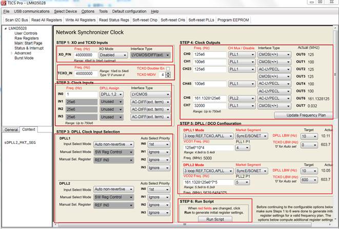
Once steps 1-6 are configured as desired, check that the reference input monitors have a valid configuration as well. The reference input monitors are just below the main steps in the main page.
The LMK05028EVM gives a step-by-step guide to connecting to a device. Even if the EVM is not being used, the guide is still valid for connecting TICS Pro to an LMK05028 device on a different board.
Under the "Advanced" tab in TICS Pro for the LMK05028, there is an EEPROM page which includes the option to export the GUI settings to an EEPROM file. You can program the EEPROM from this page, or by pressing the "Program EEPROM" button on the top bar.