This thread has been locked.

If you have a related question, please click the "Ask a related question" button in the top right corner. The newly created question will be automatically linked to this question.

PCA9554: PCA9545 digital inputs damaged caused by too long high rise times?

Part Number: PCA9554

We use a PCA9545 I2C Port Extender Chip.
In our application, we use the 8 Digital I/O-lines as inputs (also programmed by software).
Sometimes, we don't know when and why, one or more input's will be damaged or don't work correctly.
When this happens, it's not possible to read the status of these input pins, normally we see a high, when this input was damaged.
We are searching for the root cause of this failure, but we can’t solve it up to now.

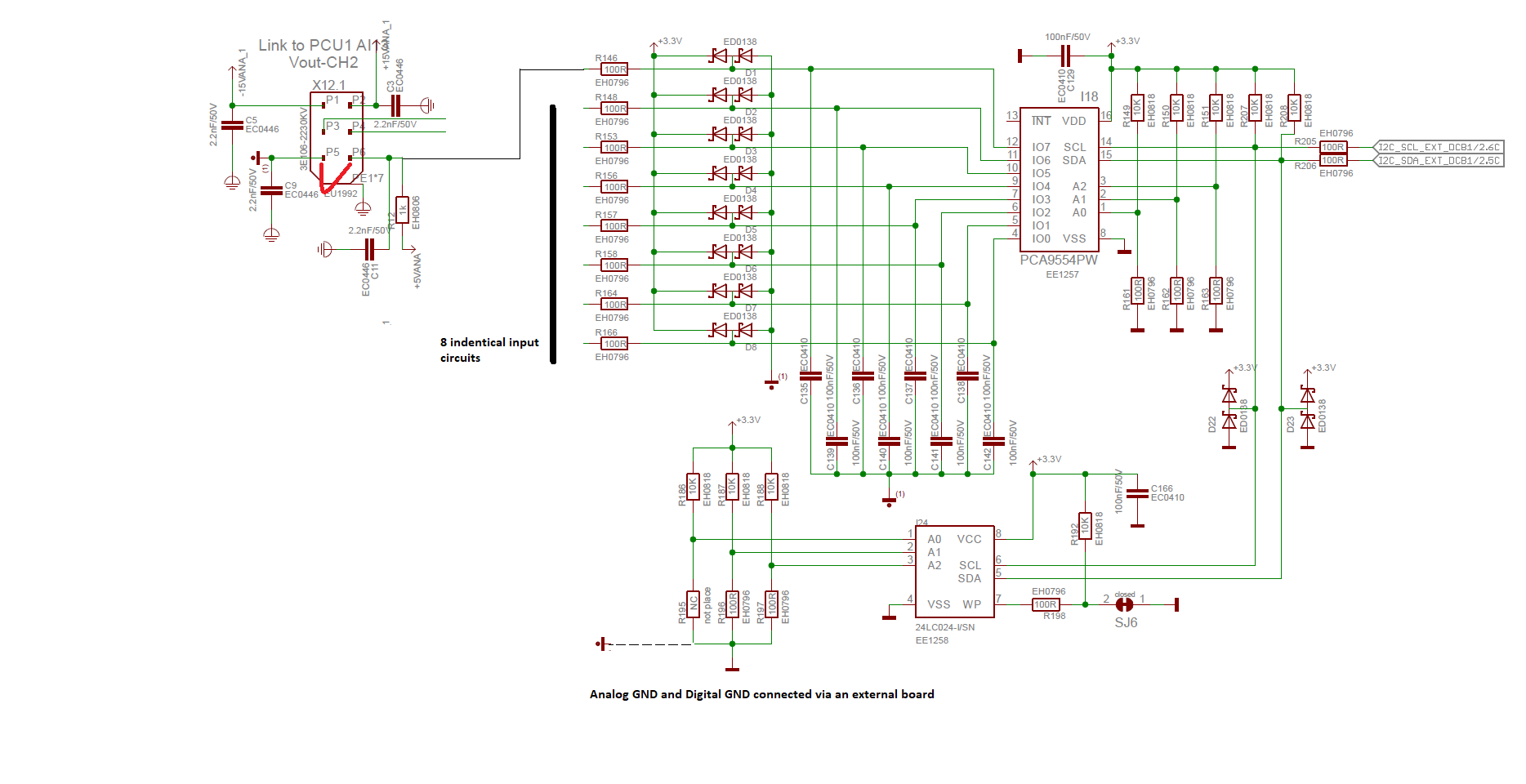
We have this inaccurate circuit design at the digital inputs:
In front of all of these digital inputs we use at each pin a RC-low-pass-filter.
The designer of these board placed 1.1kOhm to +5V (when it goes to High) and 100 Ohm (when it goes to LOW) and 100nF to ground.

The rise and fall times of the Port-Pin’s at IO0 .. IO7 are very high, much too high, I guess ..

  • Rise time at a Port-pin IOx:: Tau = R * C  --> 1.1kOhm * 100nF = 110uS
  • Fall time at a Port-pin IOx: Tau = R * C  --> 100Ohm * 100nF = 10uS

It’s more unknown instead of a common knowledge in the electronics family, I guess, rise and fall times of CMOS input circuits mustn’t be higher than 100ns …1us max, otherwise a Schmitt-Trigger input should be used. Unfortunately, this max. rise and fall times of the Digital I/O-Pin’s can’t be found in a datasheet ….

My question to the application engineers of TI and to the community:

Do you see a plausibility to destroy an input circuit by driving these inputs with this high rise times which are longer than 50 us in our application?

May calculation of the rise time at the dangerous area between TTL low and TTL high:
Tau = 110us  --> from max. TTL-low level of 0.8V to the min TTL-high level of 2.0V -->  I would say, half of Tau is a correct value during the transition --> so I think it’s more than 50us

  • Hey Alois,

    I haven't heard of anything like this before (slow rates on an input causing damage). The worst you would likely do is just cause higher shoot through currents which would result in a larger "leakage" current through Vcc.

    "Do you see a plausibility to destroy an input circuit by driving these inputs with this high rise times which are longer than 50 us in our application?"

    I don't think so.

    Do you have a schematic of the device we can review? I'd like to see if I spot anything else that may cause damage to the device. Also, what are the I/O ports actually connected to?

    Thanks,

    -Bobby

  • Hello Bobby,

    many thanks for your replay and sorry for my delay of my answer ..

    I refer to this Application note from TI: SCBA004D–July 1994–Revised September 2016 - Implications of slow or floating CMOS inputs.pdf
    In this application note the author describes exactly what you also mentioned - a larger VCC current will be seen during long rise or fall times.

    I don't know, can these higher currents destroy a chip?

    I added the circuit part in which we have this unknown PCA9545 chip error.
    This circuit detects, if a connector is connected to X12.x ( 8 identical connector detection circuits are linked to one PCA9545-chip)
    At X12.1, we  make a bridge between pin P5 and P6 when a connector is connected, means, we pull the voltage from +5V (via pull up resistor R12) to GND, indicated by the red line at X12.1.

    I wrote in my first blog, sometimes, we don't know when and why, one or more input's of tthis PCA9545 will be damaged or don't work correctly.

    When this happens, it's not possible to read the status of these faulty input pins (sometimes one or more pins, never all pins).
    We always read a high from the chip, when this inputs are damaged, but the connector pulls the input levels to low and we should read a low.

    We are looking for the root cause of this failure, but we can’t solve it up to now.
    We also discussed, if ESD could be the reason, but we think this isn't the case, in our protuction and EOL line, we are very carefully regarding ESD.

    Thanks, Alois

  • Alois Lang1 said:

    Hello Bobby,

    many thanks for your replay and sorry for my delay of my answer ..

    I refer to this Application note from TI: SCBA004D–July 1994–Revised September 2016 - Implications of slow or floating CMOS inputs.pdf
    In this application note the author describes exactly what you also mentioned - a larger VCC current will be seen during long rise or fall times.

    I don't know, can these higher currents destroy a chip?

    For our devices (I2C devices), it's unlikely something like this would destroy the chip in a short amount of time. I've talked about this with another engineer before who suggested something like a floating input could cause problems/damage in 10~20 years time..... I'm not 100% sure if this claim is true though.

    I added the circuit part in which we have this unknown PCA9545 chip error.
    This circuit detects, if a connector is connected to X12.x ( 8 identical connector detection circuits are linked to one PCA9545-chip)
    At X12.1, we  make a bridge between pin P5 and P6 when a connector is connected, means, we pull the voltage from +5V (via pull up resistor R12) to GND, indicated by the red line at X12.1.

    I wrote in my first blog, sometimes, we don't know when and why, one or more input's of tthis PCA9545 will be damaged or don't work correctly.

    When this happens, it's not possible to read the status of these faulty input pins (sometimes one or more pins, never all pins).
    We always read a high from the chip, when this inputs are damaged, but the connector pulls the input levels to low and we should read a low.

    We are looking for the root cause of this failure, but we can’t solve it up to now.
    We also discussed, if ESD could be the reason, but we think this isn't the case, in our protuction and EOL line, we are very carefully regarding ESD.

    Thanks, Alois

    Do you have scopeshots of what the signal looks like when you connect to the device? It may be some kind of instantaneous hot plug event is causing the damage. I've seen a cause where someone tried to plug a device into one of our inputs of our I/O expanders and the initial connection caused a 22V spike on the input. Something like this could break our device.

  • OK, this is an very helpfull hint, we will check this connection behavier and measure, if we see a voltage spike.
    I'll answer when we have mesurements, thanks in advance,

    Alois