This thread has been locked.

If you have a related question, please click the "Ask a related question" button in the top right corner. The newly created question will be automatically linked to this question.

TPD8S300A: TPD8S300A FLT pin status without type C load connection

Part Number: TPD8S300A
Other Parts Discussed in Thread: TPD8S300EVM

Hi team,

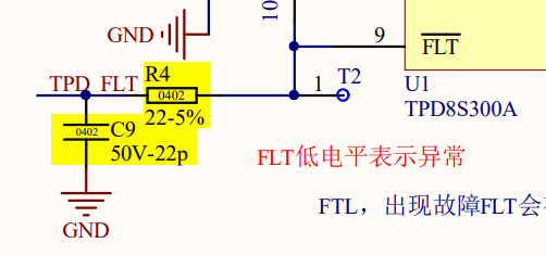
My customer is testing TPD8S300A, but they find the FLT pin is always asserted to low with 400mV no matter connected with type C device or not. Even we did have external pull up to 2.7V~5.5V.

do you think this is abnormal?

pls help review schematic if abnormal and help us correct. thanks.MTouchⅡUSBV10A_TPD8S.pdf

  • Hello,

    Please try depopulating the bypass capacitor and resistor on the fault pin, highlighted below: 

    The only recommended connection for the fault pin is a pull up resistor. Your resistor of 100k is a recommended value for this pull up resistance, so you can keep this connection. 

    Also, the unused Dx pins must be connected to GND.

    Thanks,

    Emma

  • Hi Emma,

    My customer is testing TPD8S300A protection function thur. connecting the high voltage to CC1 pin directly, would you please help confirm this test is correct or not?

    In below circuit, CC1 is connected to high voltage to test the FLT waveform to see the protection performance.


    1. CC1 is normal without high voltage, FLT is 3.3V
    2. CC1 is connected with 10V, FLT output 5V
    3. CC1 is connected with 15V, FLT output abnormally and on/off re-start, output abnormal voltage is 2-3V
    4. Then CC1 connect with 20V and we see FLT has no output, we suspect the chip is abnormal or damaged.

    do you think this setup has any problem and how about this test result?

  • Hello,

    I will test on an EVM and get back with you with the results early next week. 

    Thanks,

    Emma

  • Hello,

    Did you depopulate the capacitor, resistor, and disconnect the FLT pin from ground, as recommended above? The FLT connection should look like this: 

    In terms of the test setup, shorting the CC line to a high voltage is a standard test to ensure that the device will protect your system. This is described in the TPD8S300EVM user's guide: 

    J2 refers to one of the test points on the TPD8S300EVM. You could try using a board that discharges 20 V over a capacitor when plugged in, as this is a recommended test. For more information on proper ESD testing methods, use the application report http://www.ti.com/lit/an/slva711/slva711.pdf

    Thanks,

    Emma