Part Number: TCAN4550EVM
Other Parts Discussed in Thread: TCAN4550, MSP430FR6989, , BOOSTXL-CANFD-LIN
Hi team
I want to configure the TCAN4550 into controller mode, send CAN frame via SPI interface and then check the output on GPO2. Can you tell me how to configure the HW connection and SW configuration to achieve this?

I have one MSP430FR6989 Launchboard and TCAN4550EVM, the reason I choose MSP430FR6989 as the MCU board is that I found this device number in the TCAN4550 drive code.

I have done some work:
For HW connection
TCAN4550EVM
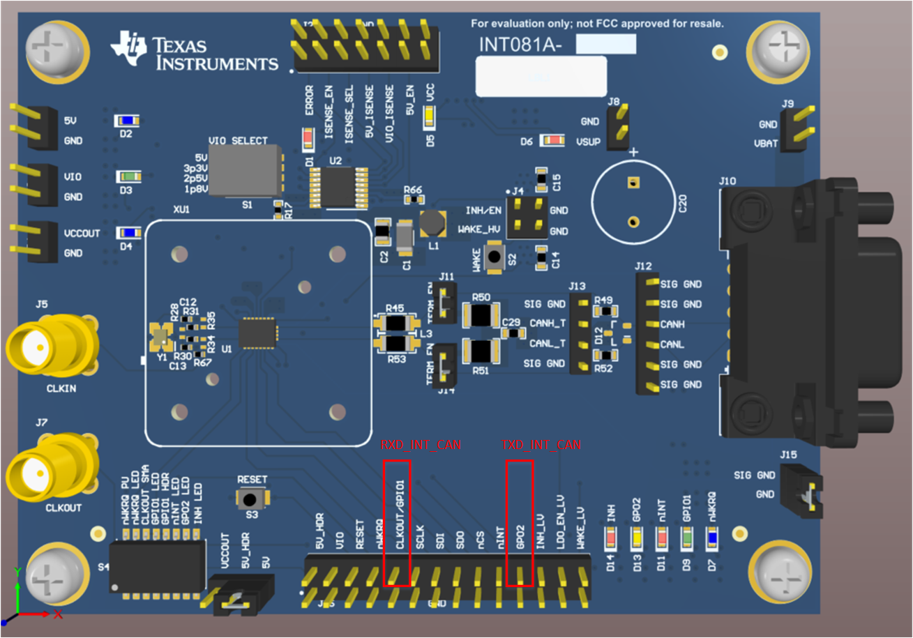
- TCAN4550EVM is powered by a DC source through J8(->VSUP) on TCAN4550EVM.
- VIO SELECT(S1) is chosen to be in 3.3V output.
MSP430FR6989 LaunchBoard
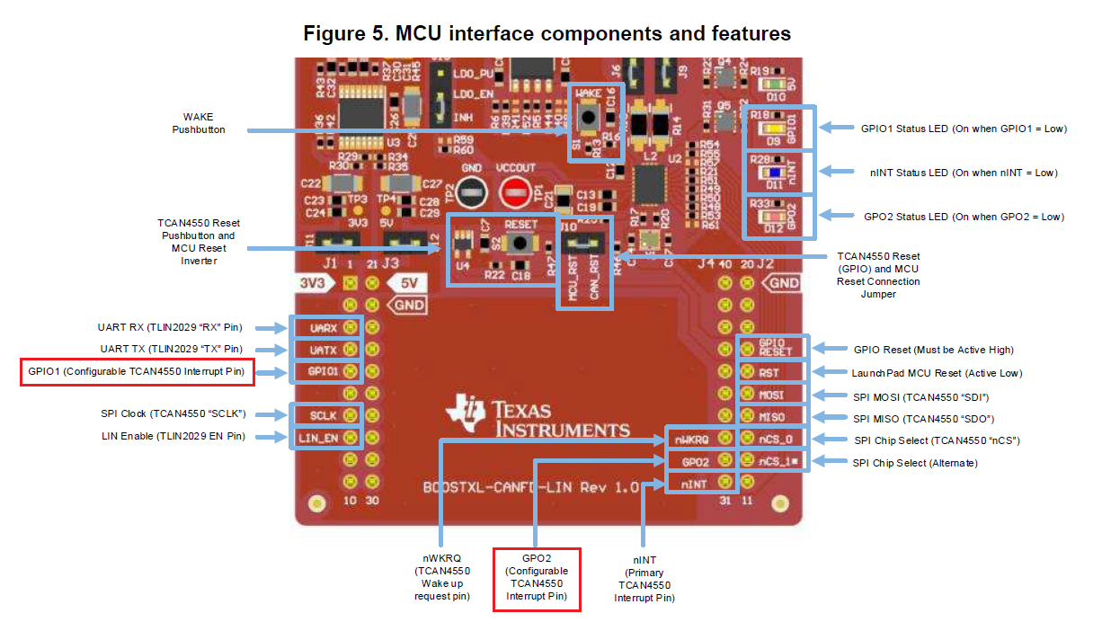
- P1.4 -> SPI CLK
- P1.6 -> MOSI
- P1.7 -> MISO
- P2.5 -> SPI CS
For SW configuration
- TCAN455x Driver Library Demo is the reference code, which is from the TCAN4550 product folder page.
-
I add TCAN4x5x_Device_EnableTestMode(TCAN4x5x_DEVICE_TEST_MODE_CONTROLLER) after the Init_CAN() to try to make TCAN4550 into controller mode
... ... ... ...
/*********************************************
* Everything at this point is for TCAN4550 *
*********************************************/
Init_CAN(); // Run the main MCAN configuration sequence. The bulk of the configuration is in this!TCAN4x5x_Device_EnableTestMode(TCAN4x5x_DEVICE_TEST_MODE_CONTROLLER);
/* Define the CAN message we want to send*/
TCAN4x5x_MCAN_TX_Header header = {0};... ... ... ...
-
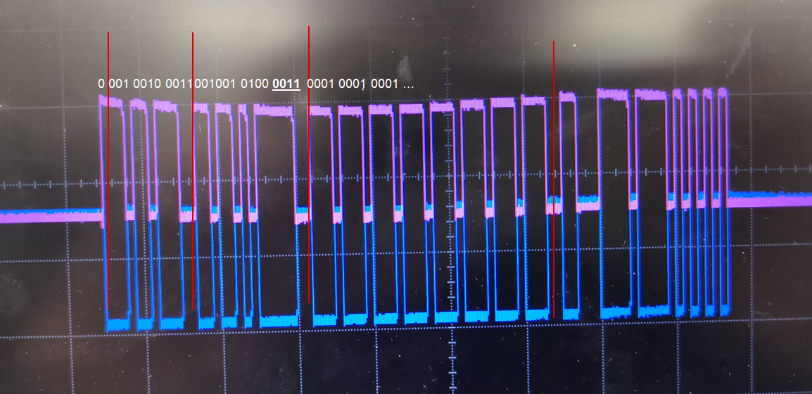
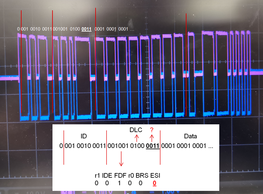
To detect the output on GPO2 using the following code.
TCAN4x5x_MCAN_TransmitBufferContents(1); // Request that TX Buffer 1 be transmitted
TCAN4x5x_MCAN_TransmitBufferContents(0); // Now we can send the TX FIFO element 0 data that we had queued up earlier but didn't send.
Can you tell me what else I still need to do to accomplish my goal?
Thank you.
Shawn Wang
shawn-wang@ti.com