This thread has been locked.

If you have a related question, please click the "Ask a related question" button in the top right corner. The newly created question will be automatically linked to this question.

TPS65987D: TPS65987D

Part Number: TPS65987D
Other Parts Discussed in Thread: TPS65987, TPS65981

Hi Team,

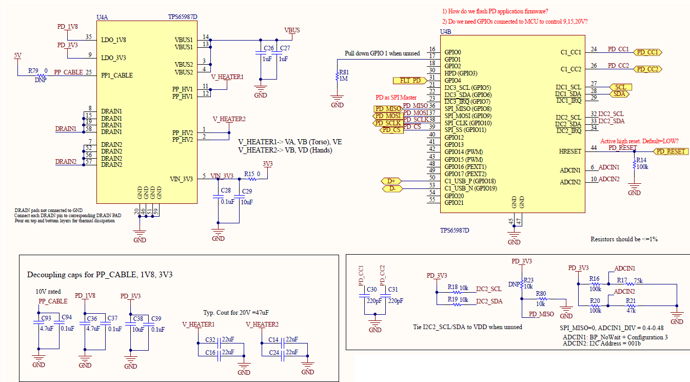
I am encountering the same problem that our module will disconnect from a PD charger after downloading patch bundle.  Our module comes  with the setting (SPI-MISO=0; DIV=0.34)

BP_ECWait_internal Infinite Wait

The EC on the module follows the process below to download patch bundle:4604._5563B783_.PNG (1138×588)

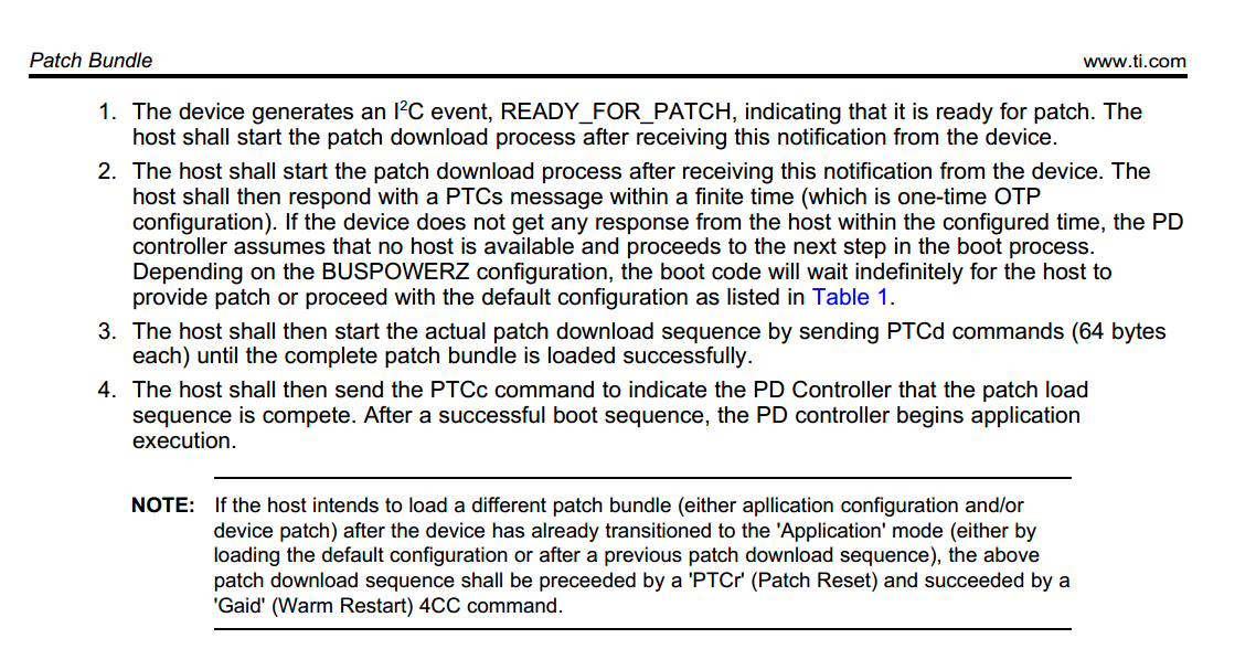
At the beginning, the firmware in EC could read out the mode "PTCH", but could not read out the event flag: READY_FOR_PATCH, from the register 0x14 (the first byte read out is 0 meaning there is no data following). After reading a few times,  the firmware proceeds to send commands, PTCs, PTCd and PTCc as above to download the bundle and all these commands executed successfully. Then the firmware read out the mode as "APP". So far so good, but then the module disconnect from the PD changer unexpectedly. The Patch bundle is got from this process: With TPS65987DJEVM and Applicatin Customization Tool, create a new project( Standard UFP only as recommended) for TPS65987DDH, then import settings from device with EVM setting: SPI-MISO=0,  DIV=0.44 (BP_NoWait Configuration 3), then save binary to get the bundle. Actually after sending PTCc, even if the firmware did not run any commands, our module still disconnect from the PD charger.   Could you tell me what the possible reason is for this problem? thanks in advance.

  • Hey Jeff,

    Which version of the configuration tool are you using and what Firmware image are you using?

    Is the EVM in a dead battery condition and it disconnects from the charger? If so, are you clearing the dead battery flag?

  • Hi Adam,

    Thanks for your response. The version is :TPS65981_2_6_7_8 Application Customization Tool, GUI Version : 6.1.1  and the firmware image is TPS65987_88_F707_10_08.bin.

    I just use EVM to produce patch bundle. As I described in my last post, with the setting: SPI-MISO=0,  DIV=0.44 (BP_NoWait Configuration 3) on the EVM, the power source bits read from the 0x26 register is 10b (Dead Battery flag is set). 

    The problem of disconnects exists on our custom module. Do I need to clear the dead battery flag in my custom module? How?

    Regards,
    Jeff

  • Hi Adam,

    I think I solved the issue with different hardware settings: In my module, I changed the settings to the same one as on the EVM, SPI-MISO=0,  DIV=0.44 (BP_NoWait Configuration 3).  When the module starts up, the firmware read out the mode of PTCH and then after get READY_FOR_PATCH successfully from 0x14 register, it proceeds to patch download process. After finish the process, the firmware can read out the mode of APP without reset. 

    Now I have a new issue: I want to close both internal power paths,PP1 and PP2, but only PP1 does.  I checked the register settings and the 0x27 Global System Configuration register can be read out by my firmware as: 0x70-30-00-00-14-14-00-00-00-00-00-12-00-01 that means both paths are enabled, but 0x26 Power Path Status Register read out as 0x1-40-00-00-00-c0  that means only PP1 enabled. Could you help find out if there is any problem with this settings?  Thanks!

    Jeff

  • Hi Jeff,

    Are you wanting to close both power paths at the same time? If so, would you be able to elaborate on what system this is going into and why you want both paths to close at the same time?

  • Hi Adam,

    Yes, we want to close both at the same time. In our system, there are heating elements on it with maximum of 1.5A consumption. I know each switch can handle this current, but our initial idea is just for lowering load on each switch. 

    Regards,
    Jeff

  • Hi Jeff,

    You must put the PD controller into Power Duo Mode, which can be done in register 0x27. Enable both internal power paths as a sink, and then check the box in register 0x27 for 'Power Duo Mode'. This should fix your issue

  • Hi Adam,

    Thanks for your answer. It works in the Evaluation Module, but unfortunately not on my board.  Actually my firmware can read the setting from the register 0x27 on my board as 

    0x70-30-00-00-14-14-00-10-00-00-00-12-00-01.  This is exactly the same as the setting in the  Evaluation Module, but readout from the 0x26 on my board is 0x1 40 00 00 00 c0 that indicates only PP1 enabled. Could you see any other possible reason for that?  Thanks!

    Regards,
    Jeff

  • Hi Jeff,

    Do you change the connections on the EVM to where PPHV1 and PPHV2 are connected to each other? By default, they are not connected to each other.

    Also, would you be able to share a snippet from your schematic showing your connections to VBUS and PPHV1/PPHV2 of the PD controller?

  • Hi Adam,

    I did not change connection on the EVM, actually your instruction about Duo mode works on the EVM. Here is our design for the part of PD controller. The V_Heater1 and V_Heater is connected to different loads, but I think the loads are almost equal. 
    Since now only one power path closed(PP_HV1), we temporarily hack the board and connect  V_Heater1 and V_Heater together. In this way, we make our module work.
    Regards,
    Jeff
  • Hi Jeff,

    Yes, that is the problem then. If you close both of the internal power paths at the same time, VBUS1 and VBUS2 must be connected to one another, and PPHV1 and PPHV2 must be connected to each other. PPHV1 and PPHV2 are not connected to each other, but since one of the connections is not pulling a load, there is no issue. Since you have two different connections, each pulling their own load, believe this to be causing issue. Moving forward, if you want both of the internal power paths to close at the same time, you must connect V_HEATER1 and V_HEATER2 together.

  • Thanks, Adam.

    I think this will solve my issue.

    Regards,
    Jeffrey