This thread has been locked.

If you have a related question, please click the "Ask a related question" button in the top right corner. The newly created question will be automatically linked to this question.

SN65HVD1176: Bias resistors and termination resistors values calculation in the dual fail-safe biasing application

Part Number: SN65HVD1176
Other Parts Discussed in Thread: PROFIBUS,

Hi All,

 I have a questions for bias resistors and termination resistors calcultions.

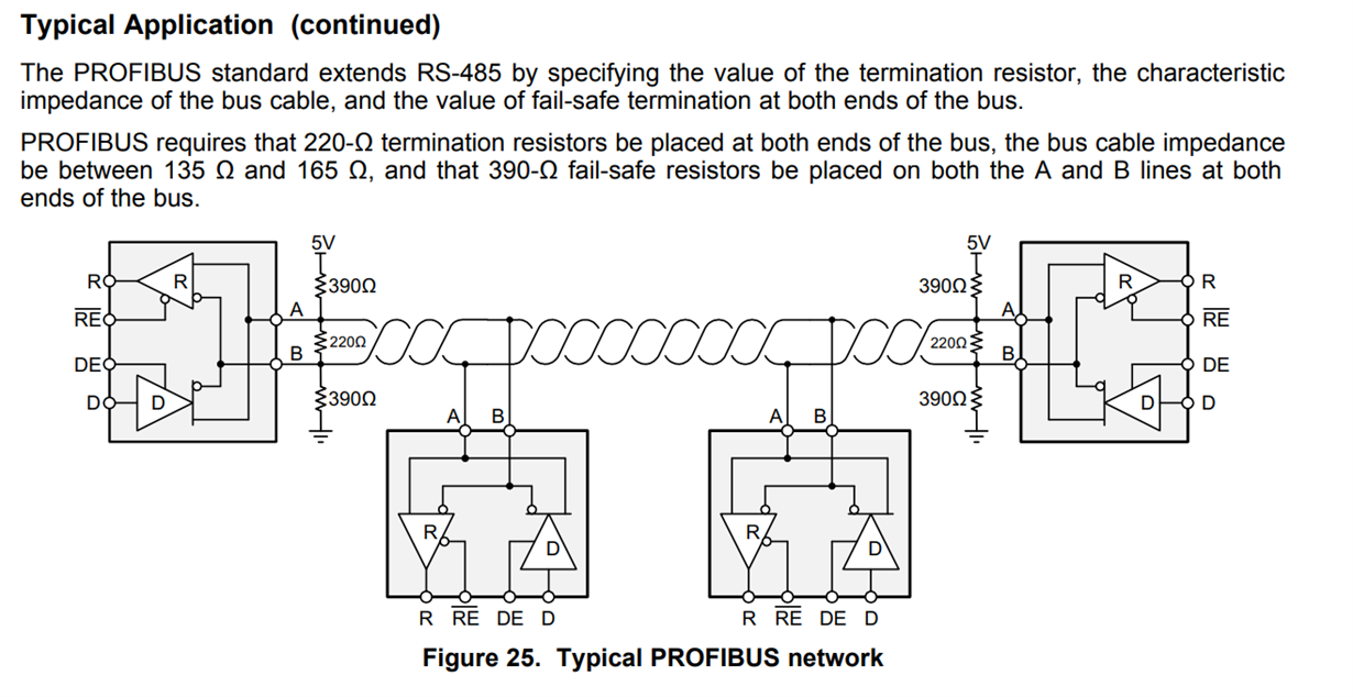
 The Profibus cable Impedance is 150R (type: 6XV1830-0EH10 ) and power is 5Vdc isolation. As learn datasheet's SN65HVD1176, I noted bias resistor is 390R and termination resistor is 220R. Can I have more details for bias resistor and termination resistors values come from? 

  • Hi Eric,

    Typical termination values are selected to match the impedance of the cable being used. Choosing these values to match closely improves reflective dampening. Here's a Technical Article that gives an overview of RS-485 Termination Basics: 

    RS-485 basics: When termination is necessary, and how to do it properly


    Failsafe Biasing Networks hold the bus in a valid state when the bus is open, shorted, or idle. This is important because the RS-485 defines an indeterminate region between positive and negative input thresholds. Resistors for this network must be chosen so that they are strong enough to bias the bus out of this indeterminate range while still allowing transceivers to drive a valid LOW signal. Here is an article regarding Failsafe Biasing Networks including calculations:

    RS-485: Passive failsafe for an idle bus


    Let me know if you have any questions about these articles. 

    Regards,

    Eric Schott

  • Hi Eric,

     Tks for your comments.

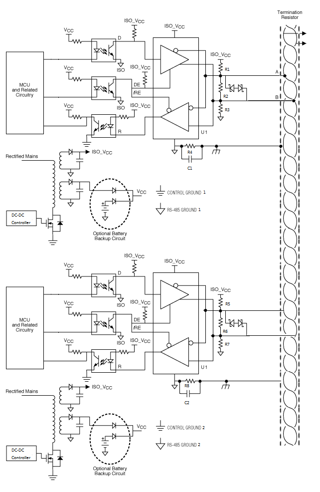
     The SN65HVD1176 is used for Profibus communication and Profibus loop is configure to dual fail-safe biasing. The diagram as following.

     1. For bias and termination resistors values: I'm try to as per above calculation to calculate bias and termination resistors values, unfortunately the bias and termination resistors values cannot similar to 390R and 220R. Can I have your calculated processing for reference? This doc. also being reference (https://www.renesas.com/us/en/www/doc/application-note/an1986.pdf). 

     2.  Whether the two A/B wires within each twisted pair consist of a signal wire and a return wire? The signal return path is unnecessary? Pls suggestion. 

    BR,

    Xiaobing (Eric)

  • Hi Eric,

    1. The calculations in both documents are generic for worst-case scenario that still conforms to RS-485 specifications. When reducing out all Rt and Req values to the constant 27.8 Ohm (based on allowed common-mode loading and line-matching constraints for RS-485), the equations in both documents can be used to solve for Rfs in the same way. We will also use the worst case supply voltage Vs = 4.75V and noise level Vab= 0.25V. 

    This specifies the maximum value of the failsafe resistors. In a system with less loading and more favorable line-matching, this value will extend to allow greater resistor values. For example a system with two 150 Ohm termination will have a maximum allowed Rfs closer to 680 Ohms. 

    Note the minimum value for these resistors is dependent on the driver strength and their ability to overcome the external biasing to drive a valid LOW. 

    2. The twisted pair are both signal wires. The RS-485 standard defines a differential line driver and receiver system which provides better immunity to signal noise and ground shifts than similar single-line methods. These transceivers drive opposite polarity signals on the A and B lines which are interpreted by the differential receivers on the bus. Let me know if this makes sense.

    Check out this Technical Article describing the basics of the RS-485 driver to better understand how this twisted pair cable is used to its strengths.

    RS-485 basics: The RS-485 Driver

    Regards,

    Eric