This thread has been locked.

If you have a related question, please click the "Ask a related question" button in the top right corner. The newly created question will be automatically linked to this question.

DP83825I: differences datasheet vs. IBIS model

Part Number: DP83825I

Team,

A customer of mine found differences in in the swtiching levels between datasheet and IBIS model:

Parameter

Datasheet (Link)

08/2019

IBIS model (Link)

02.11.2018

VIH High Level Input Voltage

0,65 * VDDIO (1,8V) = 1,17 V

Vinh =  0.770V

VIL Low Level Input Voltage

0,35 * VDDIO (1,8V) = 0,63 V

Vinl =  0.330V

Is this really the case?


Parameter

Value

Note

Positive Overshoot:

0.0 V


Negative Overshoot:

11.33 mV


Avg rise time:

427.989 ps


Avg fall time:

976.861 ps

Fall time way longer than rise 

Thanks,
  Robert

  • Hi Robert,

    I will review the IBIS model for the DP83825I and provide an answer on what signal the VinH/VinL thresholds are in reference to by Thursday (4/2).

    Can you please include what device configuration you are using and which set of pins and you are measuring the rise time, fall time, and overshoot on? This will help to provide an idea of the expected behavior and explanation if necessary.

    Regards,
    Justin 

  • Hi Justin,

    we asked the question to our FAE Robert, so i can provide the requested information directly. 

    1. The issue with the high/low level Input voltage threshold we see at the Input Pin TX_D0, but there is only one model (bc33mvuhyfz_mode_select_1) inside für 1.8V, so this issue is present for all Input / BiDir Pins.

    Ibis-File of DP83825

    [Model Selector] bc33mvuhyfz_mode_select
    bc33mvuhyfz_mode_select_1 1.8V operation
    bc33mvuhyfz_mode_select_2 3.3V operation

    [Model] bc33mvuhyfz_mode_select_1
    Model_type I/O
    Polarity Non-Inverting
    Enable Active-Low
    Vinl = 0.330V --> Here is the threshold defined
    Vinh = 0.770V -> Here is the threshold defined

    2. The second issue we see on the Pin RX_D0, we noted before, there is only one Model for 1.8V inside the file, this issue is present for all Output/BiDir Pins.

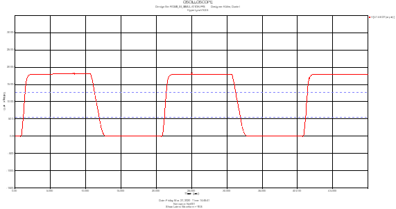
    Here a screenshot from Hyperlynx for a 50 Ohm transmission line of 6 cm at Receiver side. 

    Regards,

    Daniel

  • Hi Daniel,

    I agree that the IBIS model on the DP83825I website appears to be incorrect. I am working with our design team to update and verify the IBIS model. 

    The fall time being about two times the rise time is in-line with our validation results so that is correct in the model.

    Regards,

    Justin