This thread has been locked.

If you have a related question, please click the "Ask a related question" button in the top right corner. The newly created question will be automatically linked to this question.

TCAN1051GV-Q1: How to set the termination resistor network in multiple TCAN1051-Q1

Part Number: TCAN1051GV-Q1
Other Parts Discussed in Thread: TCAN1051-Q1

Hi Expert,

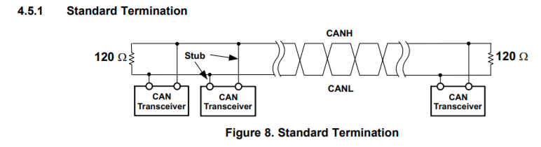
My customer is using multiple TCAN1051-Q1 in their design and wants to check what is the correct implementation of the termination resistor?

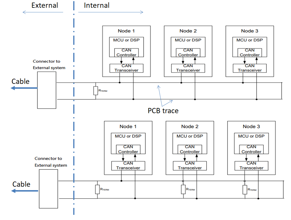
My understanding is like datasheet drawing only one set of termination resistors is needed at the connector to the external. Or would you recommend termination resistors at all transceivers?

Would you please check which drawing is the correct implementation? 

Thank you.

Best Regards,

Wei-Hao

  • Hello,

    Typically you would use two termination resistances on the bus, one for each end of the network. Since the termination resistances combine in parallel, using more than two per network may result in an overall bus resistance that is too low.

    Regards,

    Max

  • Hi Max,

    Do you mean adding two set of termination resistors on the bus, one close to the connector and one close to the end of their board? How about the resistance? should they double the resistance to make overall resistance 120ohm?

    Can you provide a drawing for better understanding? 

    Thank you.

    Best Regards,

    Wei-Hao

  • Hi Wei-Hao,

    In a CAN network, termination should be placed at the end-nodes which are the greatest cable length away. The termination value of 120-ohms is used to match the cable impedance to reduce signal reflections. Using two 120-ohm termination resistors in the system will present a 60-ohm equivalent load to the transceivers. If more than two of these resistors are added, the equivalent load will become larger and the transceiver may be unable to drive a valid Dominant level on the bus. If termination resistors are not included at the end-nodes, signal reflections may cause distortion in the signal and corrupt the data on the bus. 

    For more information on Line Terminations in a CAN network, please refer to this application report on Controller Area Network Physical Layer Requirements

    Let me know if you have any more questions.
    Regards,
    Eric

  • Hi Eric,

    Thanks for your explanation, Does that mean we should add two 240ohm termination resistors to make equivalent load to be 120ohm? or adding only 1 set is preferable for stable operation?

    Best Regards,

    Wei-Hao

  • Hi Wei-Hao,

    CAN drivers are designed to drive a total equivalent load of 60-ohms so two 120-ohm resistors in parallel is fine for the drivers. Each termination resistor should match the line impedance as closely as possible. This value is typically 120-ohms so we recommend this value of resistor be used. Overall, two 120-ohm resistors - placed at the system endpoints - should be used which will equal a total equivalent load of 60-ohms. 

    Let me know if this makes sense.

    Regards,
    Eric

  • Hi Eric,

    Got it, it is much clear now. Really appreciated your detailed explanation.

    Best Regards,

    Wei-Hao