This thread has been locked.

If you have a related question, please click the "Ask a related question" button in the top right corner. The newly created question will be automatically linked to this question.

THVD1500: RS-485 Transceivers IC burned

Part Number: THVD1500
Other Parts Discussed in Thread: THVD1550, THVD1419, THVD2450

Hi Team,

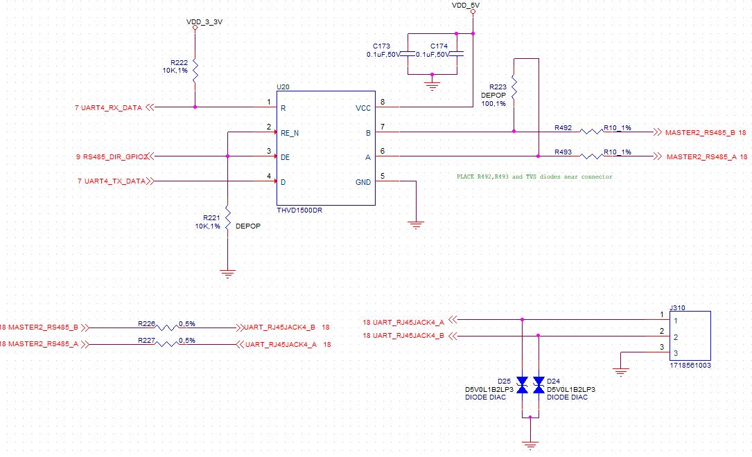
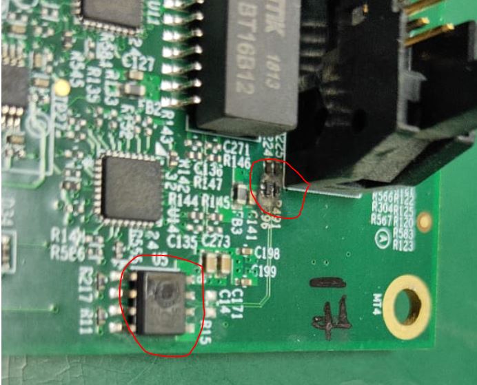
We had used the RS-485 Transceivers ( THVD1500DR) IC in our project. We had used the series resistors(10 ohm) and ESD diodes in A & B ports that ends to connector. While using in the client location the series resistors, ESD diodes and Transceiver IC were burned.

What will be possible conditions for this to happen? Can you help us in debugging this issue?

In some boards series resistors only burned , ESD protection diodes were not burned.
I have attached the schematics section of RS 485 in our boards.

  • Hi Aneesh,

    It doesn't look like your schematic was attached. (Copy and paste doesn't work unfortunately, need to attach it from the toolbar option) Can you reupload it?

    Thanks,

    -Bobby

  • Hi Bobby,
    Sorry for the delay. I will attached the schematics diagram as you said.
    Please go through our schematics.
    Please help us to find the root cause of the issue.

  • Hi Aneesh,

    To debug or design the protection, it's better to characterize the overstress events. If ESD transient current is more than the diodes can take, the extra current would flow into the IC and potentially damage it. Back to your case, the schematic looks good to me. However do you expect the ESD events could be more severe than the IEC 61000-4-2 spec? What's the power rating of 10Ohm resistor?

    Regards,

    Hao


  • Hi Hao,

    Thanks for the reply.

    We have 5 boards  damaged from client site.

    In 2 boards IC is burned and in all boards the series resistors 10 ohm (100mW)  is burned. And only in one board the ESD diode is damaged.

    We have to find the root cause, this to happen.

  • Have you ever tried to use resistor with larger power rating or size? I'm not an expert on the resistors. However I hope this app note might be helpful to you.

    Regards,

    Hao

  • Hi,

    Thanks for the app note, I will refer it.

    As from my curiosity to know more about it, Can I ask one more doubt?

    If we use ESD protection diode with the IC, does that help in the protection of the resistors too?

  • During the ESD events, the diode protects the other components by diverting transient current to ground and clamping bus voltage. However if the total amount of current is beyond the diode's limit, significant portion of current could still flow into the resistor and IC. My guess is the resistor is heated up and becomes higher impedance, which reduces the current going into the IC but damages itself.

    Regards,

    Hao

  • Hi Hao,

    In our board we had provided the ESD diode and series resistors for protection.

    But in many boards IC is damaged along with the resistors.

  • Thanks for the picture. I think the reason is over-the-limit current flows into the resistor and IC. You can try with TVS diodes, resistor and IC with higher ESD protection rating. For your information, THVD1550 is rated with +/-18kV IEC 61000-4-2 ESD, THVD2450 has +/-70V DC fault voltage protection, THVD1419 is rated with +/-2.5kV surge IEC 61000-4-4.


    Regards,


    Hao

  • Hi Hao,

    We have used ESD diode to protection.

    What are the possibilities if the ESD diode is not damaged and series resistors and IC damaging?

  • Aneesh,

    Please check out this app note as an example. You can see the TVS diode takes all the current (2A) before the GDT kicks in. Similarly I guess the resistor and IC could be damaged before the diode is turned out in your case.

    Regards,

    Hao

  • Hi Hao,

    How that can be possible for our case?

    Our design and layout (including diode placement) is good as per TI and in your view. Right?

  • Aneesh,

    Each protection (or design) only works up to certain condition. For example, if the TVS is rated for 30kV IEC 61000-4-2 but in reality the overstress at is the level 40kV, the protection scheme may fail to work. Have you tried with different resistor?

    Regards,

    Hao

  • Hi Hao,

    Sorry for the late reply.

    I have a doubt if we change the resistor to a higher package, then the chance of getting IC damage will be more without damaging the resistor.

    Correct me if it is wrong.

    Thanks and Regards,

    AK

  • AK,

    Your concern is legit. However we need to design the protection to distribute overstress current properly that each component doesn't take the amount exceeds its limit. I know sometimes it feels like a shot in the dark.

    Regards,

    Hao

  • Hi Hao,

    We cannot implement the change in the board in our client site with the higher package resistor.

    So we couldn't found the root cause of this issue without changing the package to higher one ? 

  • Aneesh,

    Unfortunately I guess it would make the debug difficult. Where are the TVS installed? Is it possible for you to change them?

    Regards,

    Hao