This thread has been locked.

If you have a related question, please click the "Ask a related question" button in the top right corner. The newly created question will be automatically linked to this question.

TUSB320: USB2.0 DRP support with USB type-C cable

Part Number: TUSB320
Other Parts Discussed in Thread: TPS2041C, TPS2051C, , TPD6E05U06, TS5USBC41, TPD4S311

Hi Team,

I have a question about USB DPR.

Here is requirement for USB and i'm looking for what is the best solution for it.
[Requirement]
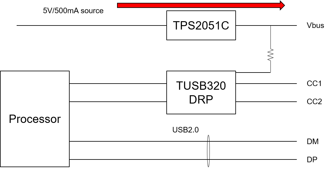
USB cable: USB type-C
USB data: USB2.0
DFP/UFP/DPR: DRP support
Power: source 5V/500mA during host/DFP. no sink during slave/UFP.

Question here is
- can below figure achieve above requirement?
- depending on ID pin state, processor has to change the state of host or slave?
- are there any concern about below figure?
- are there any other recommendation for above requirement?
- default initial value at startup is 500mA so no need to setup anything for USB2.0 current setting?

Regards,
Kai

  • Hi Kai,

    The above can work however ID should be connected to the Vbus power switch EN pin. I do recommend using I2C for this application. Accessing TUSB320 I2C registers will allow processor to know, in detail, what is happening at to the USB-C port and allows processor to respond accordingly. This also leaves a path to upgrade system as well. 

    Otherwise you will need to monitor both ID and Vbus (directly at the port or directly at TUSB320 VBUS_DET pin) so that processor can tell the difference between when UFP mode and disconnect (ID is  high in both cases). Using this method you will not be able to distinguish regular device and debug accessory. Audio accessory is possible if OUT3 is monitored. 

    In UFP mode ID pin will remain high. If Vbus power switch has active low EN pin then Vbus switch will remain open in UFP mode. 

  • Hi Malik,

    ID pin is open drain output so I should change power switch from TPS2051C(active High) to TPS2041C(active Low).

    Regarding I2C, when should Processor try to read TUSB320 I2C registers?

    My understanding is when ID pin becomes Low, it means port is Source(DFP).
    therefore, Processor should try to read I2C registers when it detects ID pin Low then changes from slave to host.
    when ID pin becomes High, and vice versa.

    If there are any other recommended way, please let me know.

    Regards,
    Kai

  • Hi Kai,

    Processor should monitor INT_N instead of ID pin. INT_N will communicate to the processor when a change has occurred at the Type-C port so I2C can be read. ADDR must be H or L for I2C to be enabled.  

    Also I recommend using TUSB320LAI instead of TUSB320.

  • Hi Malik,

    this is protection topic so I'm not sure you are right person but I picked up TPD6E05U06 as ESD protection.

    Are there any recommended 1 chip solution supporting CC1/2 and DP/DM ESD protection?
    Are there any good protection devices supporting Vbus-CC short protection with <6V(TUSB320LAI abso max) or how to protect TUSB320LAI CC pin from Vbus-CC short?

    Regards,
    Kai

  • Hi Kai,

    You will want to use parts like TPD4S311 for short to Vbus case (up to 20V) on CC and SBU. TS5USBC41 can be used on DP and DM as an OVP mux. I am not a expert on these device but you can always post a new questions with the part number and the appropriate person should contact you. 

  • Hi Malik,

    TPD4S311 OVP on CC pins is 6Vtyp ~ 6.2Vmax.
    TUSB320LAI CCx abso max is 6Vmax so 6.2V > 6Vmax.

    In actual use case, Vbus doesn't support PD so norminal voltage is 5V but do we have to protect Vbus and CC pins from any high voltage or is ESD protection enough?

    Regards,
    Kai

  • Hi Kai,

    For CC controller application Vbus is expected to be no higher than ~5V. ONly PD controllers can raise Vbus voltage. When considering non-compliant power adapters or non-complaint PD applications, it is possible to see a "hot" 20V on Vbus. This is where the 20V protection would be needed. When considering only USB-C complaint cases, ESD protection would be enough.

    Also for TPD4S311 you should refer to the C_CC1 and C_CC2 (connector side) pins abs max range for the correct values.