This thread has been locked.

If you have a related question, please click the "Ask a related question" button in the top right corner. The newly created question will be automatically linked to this question.

TUSB1064: AUX channel issue in DP 2 lane application

Part Number: TUSB1064
Other Parts Discussed in Thread: TPD6S300

Hi all,

 My customer use TUSB1064 in their docking product. We test GPIO and I2C control, but

1. There's only 1 side (FLIP = high) with DP display. If Flip = low, we will not see display on DP monitor.

2.  When we bypass aux signal, DP can be display... (connect AUXP/AUXN signal to AUXn/AUXp directly)

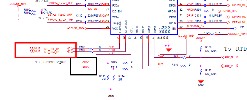
About the impedance on AUX / SBU trace, there's 2M pull down near connector, 2M pull down near TUSB1064's SBU, and another 1M pull up / pull down resistor is near DP bridge IC.

In ok condition, we can see aux signal is 0.06V / 3.26V. But in failed condition, aux signal is 1.68V/1.68V. If  without I2C control, can we know why we get the different result? (In both condition, U3 signal is ok).

Best regards,

Gary Teng

  • Gary

    The TUSB1064 requires the common mode voltage on AUXP and SBU2 to be min of 0 and max of 0.4V. The common mode voltage on AUXN and SBU1 is required to be min of 2.7 and 3.6V. If the common mode voltage is not right as in the 'FLIP = LOW' case, then AUX traffic will not pass through the SBU-AUX switch.

    Is the TUSB1064 FLIP being set correctly for both the 'FLIP = HIGH' and 'FLIP = LOW' cases?

    Do you have 1M pullup on AUXP and 1M pulldown on AUXN?

    What is UT0300PQKF?

    Thanks

    David

  • Hi David,

    1. In GPIO mode, only need to control flip signal in type-c cable reverse right? (CTL1/CTL0 are high for U3 + 2lane DP application).

    2. Yes. there's 1M pull up on AUXP and 1M pull down on AUXN near DP bridge IC.

    3. UT0300 is CC protection IC like TPD6S300.

    Gary

  • Gary

    1. Correct, the CTL0 and CTL1 set the USB and DP operation mode and FLIP sets the Type-C normal and flip orientation.

    2. Are they seeing this issue with more than one sources or just one particular source?

    3. If they replace the 1M resistor with 10ohm resistor, are they able to get the correct common mode voltage on AUXP/N and get display to work?

    Thanks

    David

  • Hi David,

     Customer find other issue on board and fix flip question. Thanks for your kindly help. BTW, they still have aux linking problem in some board and I've asked them to adjust 1M pull up / pull down resistor and see if any improvement. 

    Best regards,

    Gary

  • Gary

    Thanks for the update on the Flip issue.

    What issue do they have with the AUX link training? Do they have a Type-C Analyzer that can capture both the USB Type-C PD negotiation and AUX link training log file?

    Thanks

    David

  • Hi David,

     I'm not sure they have DP analyzer or not. They said they modify 1M pull up / pull down to 100K and the linking status is better. I ask them to check impedance matching question with DP bridge supplier. FYI and thanks for your kindly help.

    Regards,

    Gary

  • Gary

    They need to have the 1M pullup/pulldown on AUXP/N to be DP compliant. My proposed experiment of 10ohm was only trying to resolve the FLIP issue.

    Are they able to solve the AUX link training issue if they disable the TUSB1064 AUX snoop and have all four lanes enabled?

    Have they also tried different TUSB1064 DPEQ setting and see if it helps with the AUX link training issue?

    Thanks
    David

  • Hi David,

     No update from customer side. Will let you know if they still need help. Thank you very much.

    Regards,

    Gary