This thread has been locked.

If you have a related question, please click the "Ask a related question" button in the top right corner. The newly created question will be automatically linked to this question.

TCAN1051GV-Q1: CAN Termination

Part Number: TCAN1051GV-Q1

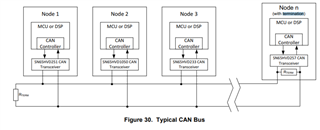
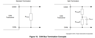
Hello, The design uses a CAN line of 7 inches,  currently, the line is terminated with a single 120ohms resistor in the middle.  in theory, it should be  two 60 ohms resistors at each end 

Can you provide a recommendation for this usage case?

thanks 

  • the CAN-BUS implementation is on a PCBA  and is 1 Mbit/s, max 

  • Hi Allen,

    It is recommended that termination resistors be placed at the end-points of a CAN network with a value that matches the characteristic impedance of the cable used in the harness (120-ohms is typical). This creates an equivalent load between CANH and CANL of around 60-ohms, which is what most CAN transceivers use to specify their driving characteristics. 

    There are different ways to implement termination at a particular node. Standard termination is simply a single resistor valued Rterm (120-ohms) between CANH and CANL. Another method is to used split termination which uses two resistors, half the value of Rterm (two 60-ohm resistors) in series between CANH and CANL, with a filtering capacitor between them. This helps stabilize the common-mode voltage and filter any common-mode noise in the system. 

    With such a small harness between your CAN nodes, it would likely be fine to only place termination in the center of the center. However, since the CAN transceivers are characterized for a 60-ohm load, the target load for the system should be close to this value. Therefore, I would recommend using a single 60-ohm resistor in the center of the network for best results here. If you're able to instead place termination at both endpoints, then each of these resistors should be 120-ohms. The resulting equivalent load would again be 60-ohms, and the transceivers would be behave as specified.

    Let me know if this is clear and if you have any more questions.

    Regards,
    Eric Schott

  • Hello, with either the 60 or 120ohms resistor install,  the voltage increases before transitioning to the remissive state.

    Similar to this:  

    https://www.picoauto.com/library/automotive-guided-tests/can-l-h/

    What is the cause of the brief rise in voltage 

  • Hi Allen, 

    I'm not sure what you're referring to in that link. Could you attach a measured or similar waveform to your reply?

    A CAN bus has three typical states:

    • a) Unbiased (off) - all CAN transmitters unpowered or in standby. Bus will rest around 0V.
    • b) Recessive (with bias) - at least one active transmitter, currently in the recessive state. Bus will rest around 2.5V (or Vcc/2).
    • c) dominant - at least one active transmitter currently driving the dominant state. Differential exists on the bus (CANH - CANL = Vdiff).

    When the transceiver(s) initially power on, they will be in the recessive state and will bias the CAN bus to ~2.5V. While transmitting data, the driver will switch states from an active dominant state (logic 0) and passive recessive state (logic 1). 

    Regards,
    Eric Schott

  • Hi Allen,

    During a reply, you can click "Insert"->"Image/file/video" to upload an image to the thread. 

    Regards,
    Eric Schott

  • Hello can you provide an email address, I'm unable to add an image  

    thanks 

  • Hi Allen,

    I've sent an email to the address listed in your E2E profile. Let me know if you have not received it.

    Regards,
    Eric Schott

  • This was resolved offline. 

    In summary, the question was referring to a higher Vod during the ACK phase of the CAN frame. The behavior is normal in CAN systems with multiple nodes, as several transceivers can be driving this bit simultaneously.

    See this thread for an example of what this looks like on the scope. 

    Regards,
    Eric Schott