This thread has been locked.

If you have a related question, please click the "Ask a related question" button in the top right corner. The newly created question will be automatically linked to this question.

DP83867CR: Invalid read data with multiple PHYs on MDIO bus

Part Number: DP83867CR

Hello,

We are having a similar issue on a custom board design as described in this post:

https://e2e.ti.com/support/interface/f/interface-forum/951336/dp83867cr-failure-with-multiple-phys-sharing-the-mdio-bus

In our design we are using a Zynq Ultrascale+ with four DP83867s connected on a shared MDIO bus.

I have checked and verified strapping, MDIO addressing, MDIO timing and the actual MDIO communication to and from the PHYs on the MDIO bus and can provide relevant scope plots.  I have also checked power and do not see any apparent issues.

The clock inputs to the four PHYs are driven by a single 25MHz clock that goes into a 1.8V 1:4 clock fanout buffer.  Each PHY gets its own clock from the fanout buffer.

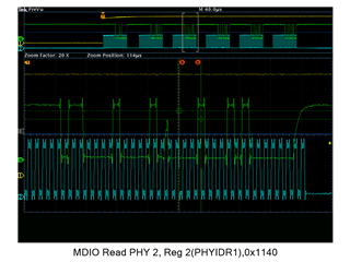
In our simplest case, we have 4 phys powered and then we assert BCMR bit 11 in one of the PHYs to transition it into power down state.  Subsequent MDIO transactions to the powered down PHY are good, but queries to the other PHYs on the MDIO bus return invalid register data which can be seen on the bus transaction.

I have verified the MDIO bus transactions and the other PHYs are being addressed and correct register address being sent, but are returning sometimes 0xFFFF, 0x00FF, 0x1140 (FYI: this happens to be the default BCMR register value) or sometimes other values.  Once the power down state of the single PHY is restored or a RESET all MDIO interfaces begin working normally.

The issue is on the PHY or state of the MDIO interface of the PHY(s)  not the host controller nor FW driver.

Is anyone familiar with this issue or state of the MDIO interface and can provide how this issue was resolved?

Thanks,

Mike

  • Here is an example of MDIO read of PHY address 2, Register 0x0002 (PHYIDR1) and the PHY responding with 0x1140 which happens to be the default value of the BMCR register 0x0000.

    This was after PHY address 0, BMCR bit 11 was asserted.  The PHYIDR1/2 reads of PHY0 were still okay, but reads of PHYIDR1/2 of PHY address 2 and 3 each replied the same 0x1140.  PHY address and register address in each MDIO transaction were correct, but each replied with 0x1140.

    Thanks,

    Mike

  • Hi Mike,

    Does each PHY have it's own pull-up on the MDIO line, or is there only a single pull-up for the entire bus?

    We have seen issues connecting when the GND connection is not adequate. If wires are used to connect the Zynq to the MDIO lines, we could try multiple wires to connect GND. If the Zynq and DP83867s are on the same board, this should not be an issue as I assume there are GND planes connecting the devices' GNDs. 

    We are looking into other possibilities and will provide additional feedback by Wednesday this week. 

    Thank you,

    Nikhil

  • Hi Nikhil,

    Thanks for the help on this it seems kind of weird.  There are four PHYs on a common MDIO bus with one 4.7k pullup on each MDC/MDIO.  This is a high technology 16 layer PCB with 7 ground planes going throughout the PCBA.

    If you were concerned by the ringing in the scope plots above, that is not real but an artifact of the DSO zoom up-sample feature, I was trying to grab the PHYIDR1/2 reads for three of the PHYs in one scope trigger.  You can see that the 'ringing' appears on both the beginning and end of an edge of the signal showing that it is an artifact of the up-sample FIR of the scope.  I tried to attach a plot at a shorter time frame where the traces are all clean, but I can't seem to paste it at this time.

    Thanks,

    Mike

  • Hi Mike, 

    I want to try to gather more information to understand the scope of the problem better.

    You mention that if a PHY is powered down through BMCR register, the registers of the powered down PHY can be accessed, but other devices' registers cannot be accessed. When you read back the registers are you seeing garbage values or no data at all? Is this scenario true for each individual PHY (power down PHY1, PHYs 2-3 cannot be read, power down PHY2, PHY 1 and PHYs 2-3 cannot be read, etc.)

    Does holding other devices in reset help the issue?

    Are the PHYs currently connected to a link partner on the MDI side? Any improvement if removing the cable

    Is the same issue seen when holding PWDN pin low, rather than using registers to set device for power down?

    Thank you,

    Nikhil