This thread has been locked.

If you have a related question, please click the "Ask a related question" button in the top right corner. The newly created question will be automatically linked to this question.

TPS65987D: Prevent sink on power up

Part Number: TPS65987D
Other Parts Discussed in Thread: TPS65987, TPS62742, TPD6S300,

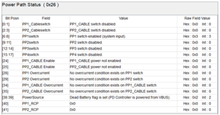
We have a TPS65987 working normally as a USB C power source UFP.  However, after turning off board power, the connected tablet repowers the TPS65987 as a power sink.

How do we prevent this and keep power off, other than adding a diode in VBUS?


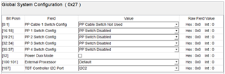
Strapping for a Boot Mode of Infinite Wait nor Configuration 1 did not help.

Thanks.

  • Hi Sam,

    What are you ADCIN1/2 pin configurations? It may be a default configuration its going into after the power off.

    Thank you,

    Hari

  • Hari,

    Boot mode = Infinite Wait

    ADCIN1 = 1.095V  DIV = .33, SPI_MISO = 1

    Our tablet is powering our board.  You would think it would not accept power.  Any idea how to keep it off?

    Thanks.

  • Hi Sam,

    Please refer to Table 6 of the datasheet to see the other options for dead battery mode. In your current configuration, it looks like the power path is enabled to sink power. You may need to switch the setting to BP_NoResponse or BP_NoWait to disable the power path.

    Thank you,

    Hari

  • Hari,
    I had originally tried ADCIN1 = gnd, MISO = 1. Table 5 says BP_NoResponse and Safe Configuration. However, the board is still powered by the tablet.
    Any other ideas?
    Thanks.

  • Hi Sam,

    I may need to see your board schematic to see if anything else could be causing this. Could you upload it here?

    Thank you,

    Hari

  • Hari,


    It appears it is recognizing there is no board power, and is setting Dead Battery flag.


    Based on ADCIN1 = 0V and MISO = 1, that should be BP_NoResponse.  V3P3 is derived from V5P0.


    However, the PP1 switch is enabled, which clearly it should not be.


    Here’s what the hardware seems to be doing:

    Ch1 yellow = 5V

    Ch2 cyan = 3.3V

    Ch3 purple = CC2

    Ch4 green = Vbus


    Why might PP1 be enabled (and the board powered), when it the configuration says disabled?


    Thanks.

  • Hi Sam,

    I'm thinking since this setting also corresponds to the Safe Default Configuration which shows that the device will operate as a Legacy sink, this is what turns on the power path. Could you try changing it to use one of the other default configurations by changing MISO = 0?

    Thank you,

    Hari

  • Hari,

    It appears BP_NoResponse is required to do nothing during dead battery mode.  And, Infinite Wait is required to do nothing when normally powered.  There appears to be no configuration that does both.  So, I’m not sure how to implement your suggestion.

    What should a BP_NoResponse and Reserved configuration do?

    Why is BP_NoResponse enabling a power switch, when it says it does not?

    Also, I floated PP cable, with no help.

    Thanks.

  • Hi Sam,

    The Configuration 1 that I mentioned would only advertise sourcing capability so you would just need to GND the SPI MISO pin, instead of tying it to V3P3 like it is now. The BP_NoResponse won't enable the power path only until the VIN_3V3 is on, which from your scope capture seems to be turning on. It looks like it initially goes to about 500mV, I'm not sure why that is. Could you tell me what it's connected to? 

    There could be other circuitry that could be interfering with the power signals as well which could cause issues. I will need to discuss with my team to see if there's anything missing. Have you tried testing on the EVM? I would also recommend referencing the Dead Battery Mode Application Note in the meantime.

    Thank you,

    Hari

  • Hari,


    Configuration:  MISO = 0, ADCIN1 = 0  undefined state

    Close to BP_NoResponse, Configuration 1, which starts at ADCIN1 = .1

    Didn’t try this.


    Configuration:  MISO = 0, ADCIN1 = .1  BP_NoResponse, Configuration 1

    Does not ‘dead battery’ power device.  Tablet states that it is charging the device.

    Does not power normally either.  App Customization Tool recognizes the device, but nothing can be changed, ever.


    Configuration:  MISO = 1, ADCIN1 = .5  BP_ECWait_External, Infinite Wait

    Does not ‘dead battery’ power device.  Tablet states that it is charging the device.

    Does not power normally either.  App Customization Tool recognizes the device, but nothing can be changed, ever.


    No, we do not have the EVM.  This seemed like a simple application…  We are running your App Customization Tool with the Aardvark I2C interface.


    A TPS62742DSSR generates 3.3V from 5V. 


    Thanks.

  • Hi Sam,

    I will discuss with my team to see if anything else could be missing. Do you happen to be using VBUS to power the TPS62742 that provides VIN3.3 to the PD controller?

    Thank you,

    Hari

  • Hari,

    The V3P3 buck converter is powered from V5P0 (which is also PP_HV1, PP_HV2, and PP_CABLE), not VBUS.

    Thanks.

  • Hari,

    So, I acquired an EVM.  The syspwr, uB bus, and var DCDC leds are on.  It seems to be able to sink.  I reinstalled the gui to ver 6.1.2.  It seems to see the FTDI.  However, it does not see the device.  Doing a sweep address range, it finds nothing, “I2C Address Sweep failed read for all addresses in range 0x0..0x7F”. 

    SPI_CLK is active, and I2C_SCL is silent (SCL and SDA both go low, but no activity).  S1, 1-6 all on.  The same happens with only S1 5-6 on.

    Any idea why the I2C is silent?

    Thanks.

  • Hi Sam, 

    I verified with my team and it seems this is currently the expected behavior. Since the device goes into dead-battery mode, it will always present the Rd and the power path will be enabled. However, if you use a device such as the TPD6S300, you can choose not to include the pull down resistors in the design for this device and this way it would essentially hide the Rd from the TPS65987D which is what you're looking to do.

    For the I2C issue, when you installed the GUI version 6.1.2 did you also install all of the latest drivers including the ones for FTDI? You could also try using the other USB ports to see if it could connect on a different port.

    Thank you,

    Hari

  • Hari,

    Thanks for confirming what seemed to be happening. 

    Do we know which power path will be enabled in dead battery mode?  If so, maybe we can float that path.  Otherwise, the TPD6S300 would appear to be an option of last resort.

    A different port fixed the FTDI driver issue.

    Thanks.

  • Hi Sam,

    I believe PPHV1 should enable as the sink path by default, however I am not sure if you could just float this when not in use. I would recommend checking with the USB PD specification document as well. 

    Thank you,

    Hari