This thread has been locked.
If you have a related question, please click the "Ask a related question" button in the top right corner. The newly created question will be automatically linked to this question.
Hi Team,
Customer uses MAX3232. MAX3232 has the abnormal waveform which resulted in the communcation fail only in 115200. 9600 speed test is ok.
Customer uses the ST3232 to replace MAX3232. The issues is disappear.
Please help review the schematic and provide your comment for the issues.
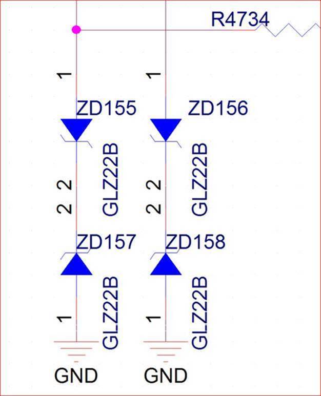
schematic
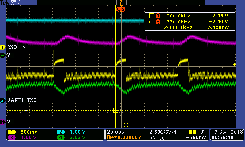
abnormal waveform(MAX3232)
the abnormal is CH1 period between a and b cursor. It suppose to be high. However, It keep at weird level.
abnormal waveform while the bus is free.
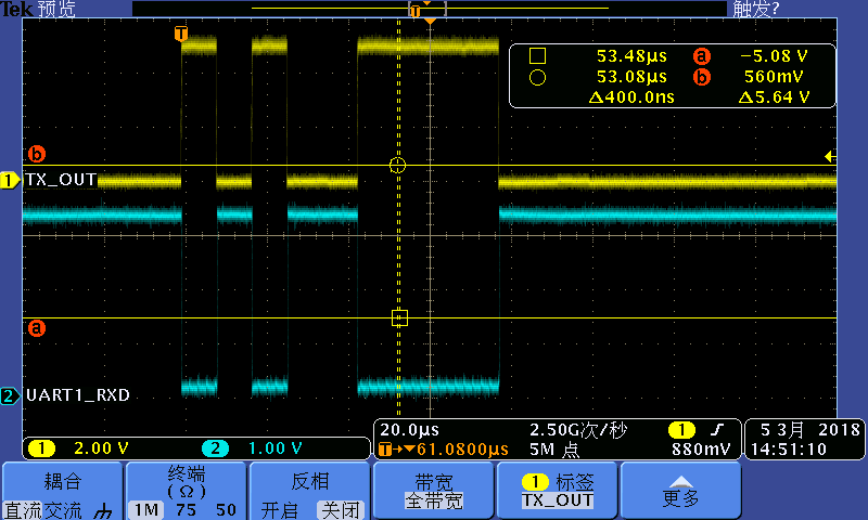
normal waveform (ST3232)
Do you TRSF3232 can fix this issues?
e2e.ti.com/.../530690
Thanks,
SHH
SHH,
The V- waveform doesn't look right, by which the voltage level should be around -5V. It looks like there are some coupling between RXD_in and V-. To debug let's check the basics first. 1) Please make sure all capacitors are rated at least 10V and no polarity concern; 2) Can you try to connect V+ cap C3 to ground instead of Vcc? 3) Can you check the ground routing of the board to be sure it's solid; 4) Please make sure zener diode protection are bipolar and can work with -5V to 5V. I'm looking forward to your response.
Regards,
Hao
Hi Hao,
1) Please make sure all capacitors are rated at least 10V and no polarity concern;
all theMLCC cap rating are 16V and no polarity.
2) Can you try to connect V+ cap C3 to ground instead of Vcc?
connect C3 to GND. the issue is same
3) Can you check the ground routing of the board to be sure it's solid;
Layout as following.
4) Please make sure zener diode protection are bipolar and can work with -5V to 5V. I'm looking forward to your response.
Zener adopt GLZ22B VZ, voltage is 21V.
BR,
SHH
SHH,
Thanks for your information. Can you please check the supply voltage and (if possible) the current? Sometimes the supply has current limit. Please make sure the power to the device is at least 3V. Another experiment you can do is to load one of the channel with some capacitors to see the situation become worse. Sorry we still cannot pinpoint the cause. But I think we will get there.
Regards,
Hao
Scott,
I'm sorry I didn't fully understand the situation. My understanding is that the abnormal waveforms from your first post came with Vcc=3V with C412=0.1uF and C414=0.1uF. But after you changed the supply to 5V with C412=0.1uF and C414=1uF, the waveforms look normal.
If it's the case, can you please check the supply waveform of Vcc=3V? MAX3232's operation range is 3V to 5.5V. If the supply is lower than 3V or has noise, MAX3232 might response differently.
Regards,
Hao