This thread has been locked.

If you have a related question, please click the "Ask a related question" button in the top right corner. The newly created question will be automatically linked to this question.

power on reset sequence for TUSB1310A

Other Parts Discussed in Thread: TUSB1210, TUSB1310A

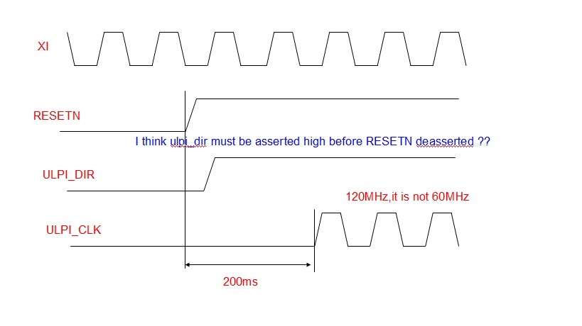
According to  figure 6-1 of data manual , ulpi_dir is asserted high after power supplies(before RESETN deasserted)

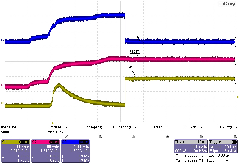
But ulpi_dir is asserted after RESETN deasserted in my verification environment.

So the strapping value can not  be latched correctly, ulpi_clk is not 60MHz.(it is 120MHz ,low power mode)

How to solve the problem?(my crystal input clk is 40 Mhz, refclksel0 =1 ,refclksel0 =1)


  • Hello,

    You are correct,

    ULPI_DIR should be asserted before.

    Could you provide more information, schematics, logic capture of the signals at power-up?

    Regards.

  • 8551.USB_PHY.pdf


    schematic in attach file

    I only want to use usb2 transfer data.

    strap pin setting:

    xtal_dis = 0 , ssc_dis = 0 , pipe_16bit = 0 , iso_start = 0 , ulpi_8bit = 0 , refclksel0 = 1 refclksel1 = 1


  • A:Use Power On Reset
      1. RESETN pin add a capacitance(10uF)        

        It will generate ulpi_clk successfully, but ulpi_dir is asserted after power on reset.
        Beacause add a capacitance, reset signal spends a lot of time to deassert.
        Then usb3 device controller sends command to TI phy during  the period of reset signal deassert.
        So i find TI phy will not send upli_nxt signal to controller.


    2.RESETN pin without a capacitance
        It will not generate ulpi_clk successfully.

     B. Use FPGA reset key
        RESETN pin without a capacitance
        It will not generate ulpi_clk successfully.


    Do i need to add a capacitance for RESETN pin?

    Is this power sequence correct?


  • Hello,

    It is starting to sound like a power-up issue.

    The voltage supplies and the reference clock have to be stable and within its operational limits before RESETN deassertion.

    How long does RESETN deasserts after the power rails are stable?

    Do not connect PHY_RESETN to RESETN and OUT_ENABLE through R521. You can connect RESETN together with OUT_ENABLE, OUT_ENABLE should be asserted only after 1.8V is stable.
    Disable SSC using the strapping option SSC_DIS.
    Make sure POWER_DOWN[1:0]=00.
    Make sure JTAG_TRSTN and JTAG_TCL are pulled low.

    Regards.

  • Hi,

    1. After i modify the reset connection and strapping value, it can generate successfully 60MHz ulpi_clk.

       But control signals output from ti phy are not correctly, ulpi_dir and ulpi_nxt  do not work.


    Because i only use USB2 tranfe, i tie a value at input port of TI phy pipe interface.

    TX_DETRX_LPBK = 0      , TX_ELECIDLE = 1   , TX_ONESZEROS = 0 , RX_POLARITY = 0,    POWER_DOWN = 2'b00

    TX_MARGIN2-0 = 3'b000 , TX_DEEMP = 2,b01 , TX_SWING =0, RX_TERMINATION = 0,


    2. I want to use USB2 transceiver, how to set PHY_MODE0/PHY_MODE1.

       How to set IOSTART strapping pin for USB2 transfer?

  • Hello,

    Try the following: set IOSTART=1, PHY_MODE[1]=PHY_MODE[0]=1

    Are you always use the TUSB1310A just as a USB 2.0 PHY? Because there are specific devices for this like the TUSB1210 and TUSB1211.

      Regards.

  • Hi,

    Because our FPGA verification environment can not meet  timing constraint of pipe3 (250MHz), we can only use USB2 transfer.

    1.  PHY_MODE[1]  = PHY_MODE[0]  = 1 only  for USB2  transceiver ,

         now  i set   PHY_MODE[1] = 0 , PHY_MODE[0] = 1 for USB3 transceiver ,but  ULPI I/F can issue correctly signal.

         How to set this signal  for USB2 transfer?

    2.

    Because i only use USB2 tranfer.

    Can i tie a value at input port of TI phy pipe interface ?  floating these pin?

    TX_DETRX_LPBK = 0      , TX_ELECIDLE = 1   , TX_ONESZEROS = 0 , RX_POLARITY = 0,    POWER_DOWN = 2'b00

    TX_MARGIN2-0 = 3'b000 , TX_DEEMP = 2,b01 , TX_SWING =0, RX_TERMINATION = 0,


  • Hello,

    1)

    Set IOSTART=1, this will isolate the PIPE interface.

    Set PHY_MODE[1]=PHY_MODE[0]=1.  This configuration is for testing but also could work to configure the PHY as USB 2 (this is just a test)

    2) Regarding your configuration of the above signals, most of them are don't care if you are not using the PIPE interface, these are the recommended settings for power-up:

    TX_DETRX_LPBK can be left floating.

    TX_ELECIDLE=1

    TX_ONESZEROS can be left floating.

    RX_POLARITY can be left floating.

    POWER_DOWN[1:0]=10b

    TX_MARGIN[2:0] can be left floating.

    TX_DEEMPH[1:0] can be left floating.

    TX_SWING can be left floating.

    RX_TERMINATION=1

    Can you provide a scope capture of the power-up sequence showing 3.3V, XI, RESETN, PCLK, ULPI_CLK, ULPI_DIR

    Regards.

  • Hi,

    1. After power on , I  find  ulpi_dir = 0.  After i deassert phy hardware reset  ,  this signal will be asserted high.

        It  causes our system ulpi_clk unstable ( ulpi_dir = 0, ulpi_data is output direction , strapping value will be changed ).

        Do i need add a pull up resistance  at  ulpi_dir ? 


  • Hi,

    What  problem will cause  PWRPRESENT = 0 ?

    PIPE3 interface setting:

    TX_ELECIDLE=1 ,  tie POWER_DOWN[1:0]=2'h0 , RX_TERMINATION=0


  • If PWRPRESENT=0 you are probably not implementing terminal VBUS.

    Connect a 90.9k 1% resistor from the cable VBUS connector to the USB VBUS terminal on the TUSB1310A and a 10k 1% resistor from USB VBUS terminal to ground.

    Regards.