This thread has been locked.
If you have a related question, please click the "Ask a related question" button in the top right corner. The newly created question will be automatically linked to this question.
Hi,
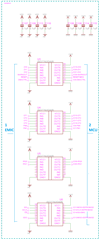
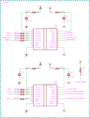
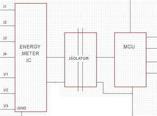
Subjected to the previous Post ADS1018, We are using Isolators between Energy Meter-ADC IC and Microcontroller (CC3220MODSF12MOBR) as shown in the block diagram below to monitor the AC Voltage and Current.
1. Kindly suggest the suitable Isolator IC for SPI pins, Pulse output pins and Interrupt pins.
Thanks and regards,
Naveen K
Hello Naveen,
Thank you for your interest in our isolation's devices. The common recommendation in SPI isolation is ISO7741. ISO7761 is also an option if more I/O is needed for additional control signals.
See Isolating SPI Signals (Rev. A), for more information and helpful links.
Best,
Andrew
Hi Andrew,
Thank you for the information and appreciated your quick response.
We are having 6 Inputs, 8 Outputs and one SPI, so we need to isolate these pins. So, we need 3 to 4 Isolators in the Board. We thought to use same part numbers for all the isolators if possible.
a. Left Side, labeled as "1 EMIC" Isolator Signal pins are directly connected to EMIC-ADC IC pins and Labeled as "2-MCU" pins are directly connected to Micro-controller pins.4th Isolator for SPI signals, GND1 and VCC1 is connected to MCU side and GND2,VCC2 is connected on EMIC side compare to other 3-Isolators are in opposite. Hope this swapping will not impacting the operations, right?
b. To protect the Isolators and MCU and EMIC-ADC each other from the Higher signal Current/Voltage, Need to place Current Limiting series resistors between EMIC-Isolator (Left Side) and Isolator - MCU (Right Side)? or not important to have current Limiting resistors?
c. SPI Slave Select(CS) pin need Pull up resistor. Pull Up resistor should be on Isolator Input pin or Output pin or any side will be fine?
Thanks and regards,
Naveen K
Hello Naveen,
Please see my comments below.
Please mark this post as resolved if all questions have been answered.
Best,
Andrew
Hi Andrew,
Thank you for the information.
Thanks and regards,
Naveen K
Hello Naveen,
Best,
Andrew
Hi Andrew,
Thank you for your support.
1.All unused input and Output should kept float or we need to pulled down or pulled up?
2. Hope Output current will be 2mA @ 3.3V VCC and it will not drive the LED directly.
3. Please review the Schematic and confirm if any modification required.
Thanks and regards,
Naveen K
Hello Naveen,
Best,
Andrew