SN6507: Some question about SN6507

Part Number: SN6507

Tool/software:

Dear Expert

I would like to ask a few questions about the application of the SN6507DGQR chip:
Application scenario, 12V input, output around 12V, transformer tie ratio 1:1,
1. To adjust the duty cycle, according to the specifications, it is necessary to increase the inductance. I have tested that the static power consumption is nearly 30mA. Without increasing the inductance, the static power consumption will be reduced by more than half, and the output will be more stable with the increase of load,
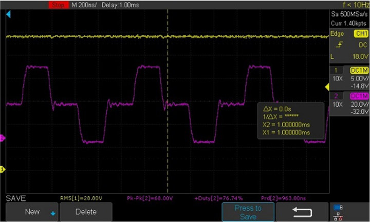
2. Can you provide a reference for the waveform of the switching frequency? The waveform I tested here is a square wave when the duty cycle is fixed at 50%, and the rest is an anisotropic wave

  • Hi Gabriel,

    Thank you for reaching out. Please find my inputs below, thanks.

    1. The typical duty cycle is set by the RDC resistor while the output inductance LMIN is the inductor that is used to filter the output and its value depends on the minimum load you are going to use. Therefore, if you increase the load, the output is expected to get stable for a given LMIN. Please use Equation (2) from datasheet to calculate LMIN.
      1. Similarly, use Equation (1) to calculate to RDC.
    2. Yes, the switching waveform is expected to change between default (48%) and duty cycle control modes. I am copying below an expected switching waveform for duty cycle of 25%.


    Regards,
    Koteshwar Rao