This thread has been locked.

If you have a related question, please click the "Ask a related question" button in the top right corner. The newly created question will be automatically linked to this question.

SN74LVC2G74-Q1: What is the sample timing of the input high/low

Part Number: SN74LVC2G74-Q1
Other Parts Discussed in Thread: SN74HCS74

Hi

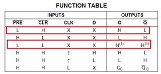
I would like to know what timing does SN74LVC2G74-Q1 sample the high/low level of input ?

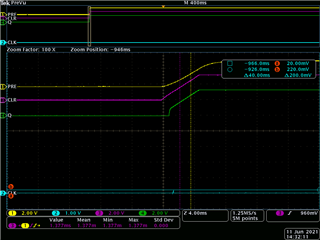
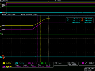
in the case below, Vcc, D, and CLR connected to Vcc. The PRE pin connected to Vcc with a RC delay.  

I discovered that the Q is outputting since the Vcc is not ready. Is that a normal performance ?

I found the Q didn't output sometimes when I reboot.

after all, I want to know the following 2 question.

1. What is the sample timing of input ?

2. I want to make Q output high without CLK input when I boot my device, how can I make it stable ?

Thank you!!!

  • Hey Deshawn,

    The Timing Requirements can be found can be found on page 5 of the datasheet.

    However, when you boot the device, the output will be unknown so it's very possible that sometimes you have Q output high and sometimes Low during your bootup.
    See this FAQ 
    [FAQ] What is the default output of a latched device? (Flip-Flop, latch, register)

    A schmitt trigger input can give you a known state at the input. A device such as the SN74HCS74 has these built in.

    Thanks,
    Rami

  • Thanks Rami.

    I have 2 further questions.

    1. The timing requirement on page 5 is input data which related to CLK. What I want to know is the timing of judging the input high or low to determine the output status. Or the timing is not important since I have to judge high/low of input in boot up process.

    2. If I use SN74HCS74 which has Schmitt trigger built in, does it solve my problem ? ( I can define high/low of input clearly even in a boot up process.)

  • When the supply voltage reaches the minimum voltage where correct operation is guaranteed (1.65 V), the /PRE input must still be low (below VIL, i.e., 0.57 V). This appears not to be the case in the second waveform. You have to use a longer RC delay.

    A device with Schmitt-trigger inputs allows you to use input signals with slow edges. (With the LVC device, the rising edge of the RC delay probably violates the Δt/Δv limit.)