This thread has been locked.

If you have a related question, please click the "Ask a related question" button in the top right corner. The newly created question will be automatically linked to this question.

CD4007UB: When I connect the CD4007UBE as a Schmitt Trigger, the voltage on pins 2,11,13 does not behave as expected. Why?

Part Number: CD4007UB
Other Parts Discussed in Thread: CD40106B

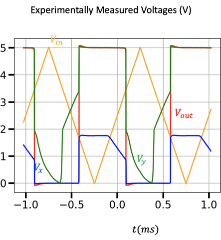
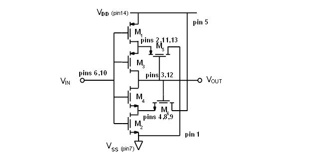
When I connect CD4007UBE as a Schmitt Trigger, the voltage on  pins 2,11,13 (Vy) does not behave as expected. These pins seem to have a capacitive coupling to ground. So Vy approaches zero when  the output is zero. Is this behavior normal? The voltage Vx (pins 4,8,9) behaves as I would expect. The output voltage seems correct, and there is voltage hysteresis. Why are the measured voltages Vx and Vy not similar in shape? Please refer to the pictures below. Thanks for your help.

  • Hi Don, and welcome to the forums!

    Is the shown waveform to be expected at the feedback nodes? I'm not entirely sure, as we don't specify or measure this type of operation for this device.

    It surprises me a bit to see Vx clamping to such a low voltage (looks like about 1.75V) -- however you are operating at 5V with a 15V nominal device -- you may see different behavior at higher voltages. I'm afraid I don't have a good point of comparison - all of our ST devices have these nodes internal to the device.

    Usually the transistors in a Schmitt trigger will be sized much smaller to reduce power consumption from the feedback circuit, and they will be sized specifically to select your thresholds based on the process characteristics. The voltage at the feedback node (Vx, Vy) will be directly controlled by the two FETs and their characteristics.

    That's an interesting experiment, however I wouldn't consider this a recommended use of the device or something practical to use in a system.

    If you're looking for a ST inverter with 18V capability, I'd recommend to use the CD40106B instead.