This thread has been locked.

If you have a related question, please click the "Ask a related question" button in the top right corner. The newly created question will be automatically linked to this question.

CD74HC165: Ends with random output state

Part Number: CD74HC165
Other Parts Discussed in Thread: SN74LV8154, PCM1794A

I built an entirely discrete logic based circuit and I have this shift register converting data from the Y bus on an SN74LV8154 to serial data and my logic design allows the shift register to load 1 extra bit so it ends on the value of the SER input (which is held low) before SH/LD goes low again but the output ends up in a seemingly random state not related to the input where it could be high or low and if it's high the output will slowly die down while oscillating at a high frequency well above the 10MHz clock source.

I have 4 of the counters in series with RCOA of one connected to the clock A input of the next which counts correctly, the clock source is a 10MHz OCXO and the rest of the project gets the clock from a decade counter and runs at 1MHz which despite the low duty cycle seems to work OK.

The problem may have something to do with the 3 state output of the counters since the output seems to fall off slowly, I could add an AND gate to the output of each shift register as a workaround but I'd have to order more and I can't fit more on my project board as it is so I'm posting here to see if there's anything else I could do.

You can see how the circuit is expected to work with the Falstad circuit simulator: https://tinyurl.com/y48e6lsl

The counters don't roll over in the simulation simply so I can see if it outputs the data correctly, the 4 counters and latches make the SN74LV8154 counters, they are then connected to the shift registers.

I'm only simulating the first 8 bits of the counters just to simplify it but you can see the register selection states.

Click the Serial In pin H for at least 1 clock cycle to trigger it

Here is a picture of my project

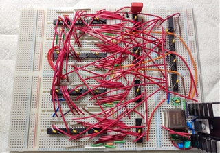
The SOT-23 by the OCXO is a 3.3v to 5v level shifter, see if you can make sense of the rest.

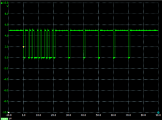
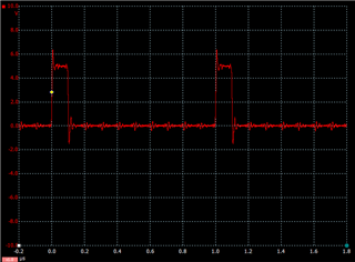
Here you can see 2 samples of the output where at each 10th microsecond is the serial stop bit followed by 8 data bits then a 1 clock pause before the next byte of data and as you can see due to the way the shift registers are connected via a NOR gate, if the output of 1 more more remains in the high state the data after it is blocked.

This is the serial clock, the overshoot is mostly due to the scope probe ground lead:

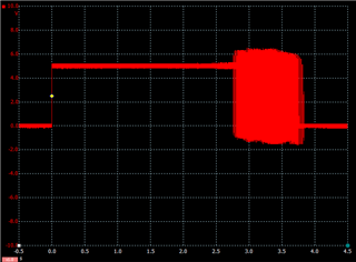
Here you can see the oscillation which happens only if the shift register output QH remains in the high state, its about 37MHz:

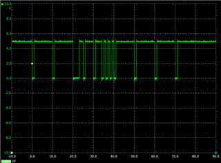
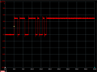
Here you can see the same QH output as above but when the serial data is transmitted, keeping in mind it will remain in a random state when SH/LD goes low:

I hope that's sufficient data ; )

  • Hi David,

    Personally, I've found that building a reliable logic circuit of the complexity you have here with breadboards is practically impossible. Troubleshooting them is equally difficult. I'm quite impressed that the circuit is working as well as you have shown -- probably a testament to the time you have taken to put this all together.

    The problem may have something to do with the 3 state output of the counters since the output seems to fall off slowly, I could add an AND gate to the output of each shift register as a workaround but I'd have to order more and I can't fit more on my project board as it is so I'm posting here to see if there's anything else I could do.

    This type of oscillation is most commonly caused by a slow transition on one input of a standard CMOS logic device - but it could also be a weak connection somewhere (gnd or vcc are common culprits that are hard to track down). Based on the fact that you mention a slow transition and the rest of the circuit is working well, you may want to take a closer look at the correlation between the slow signals and the oscillations.

    You could add pull-up or pull-down resistors at those 3-state outputs (1kohm) to give a pretty fast transition when in 3-state that could eliminate the issue.

  • I have heard the "breadboards are useless" argument and in most cases its poor grounding and overly long leads, I've made a DAC prototype using a PCM1794A with these boards where the PLL clock can be as high as 49.15MHz and it works flawlessly. I use the K&H AD series boards which are fantastic they have 6 holes per bus rather than 5 and super low capacitance. I would need 32 resistors to pull down the Y bus of the counters but I suppose I could fit them all in, if only the counters had standard CMOS outputs.

  • You're right - the reason I've had issues in the past is probably that I have old breadboards and many have been mistreated. I should get some new ones, but these days it only costs me $2 (and some waiting) to get nice PCBs, so I just go that route.

  • Mind if I ask where one can get a PCB made for so little?

  • I have to be careful what I say on here since what I say can be considered TI providing an endorsement. Just to be clear - this is my personal opinion and I use these boards only for my personal projects.

    JLCPCB is who I've been using for a while now -- usually takes about a month to get my boards. Technically it was $7 the last time I ordered them, including shipping.

  • Well I found a bunch of random 2.43K resistors and stuck them on the Y bus of the first counter to ground and now the shift register goes low when its finished outputting the data.

  • That's good - maybe not the prettiest fix, but if it works, then it works.