- Ask a related questionWhat is a related question?A related question is a question created from another question. When the related question is created, it will be automatically linked to the original question.
This thread has been locked.
If you have a related question, please click the "Ask a related question" button in the top right corner. The newly created question will be automatically linked to this question.
Hi,
I am using 2 Pin Bicolor LED where reversing polarity change its color.
Supply Voltage :3.3V
LED Specifications are
Forward Voltage: 2V
Max Current: 20mA
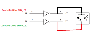
Can we use Dual inverter gate (SN74AUC2G04) for driving LED?
Datasheet Link:
I have made configurations like below.

AUC devices are not designed for 3.3 V. Use a family like AUP or LVC.
You can use either inverters (74xx2G04, 74xx2G14) or plain buffers (74xx2G17, 74xx2G34).
Without a separate resistor, the current is limited only by the output impedance of the gate itself. AUP devices (e.g., SN74AUP2G17) have about 50 Ω, for a total resistance of about 100 Ω when going through two gates, with a resulting current of about 10 mA. LVC devices are too strong and always need a current-limiting resistor.
Hi Clemens,
Thanks for suggestions.
Based on availability, i have found SN74LVC2G34 which has good output current.
Can you please help how did i know output impedance? I am not getting in Datasheet.
Also, LED module has inbuilt resistor.
Also there is a statement that "Supports 5V VCC Operation" but i have 3.3V supply, can i still use this series?
The statement that 5 V is supported does not rule out support for other voltages.
As mentioned above, an inverter in the LVC family will work.
If the LED module has a built-in resistor, then it is likely that you do not need an external one. But I cannot be specific without seeing the datasheet.
Hi Clemens,
Please find attached datasheet
https://www.mouser.in/datasheet/2/26/Apem_09152017_QS-1158415.pdf
Can you please confirm now?
Hi Deepak,
Can you please help how did i know output impedance? I am not getting in Datasheet.
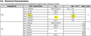
You can calculate the output impedance from the electrical characteristics table.

For example at a Vcc of 3V:
Rout = (Vcc- VOH)/IOH= 3V - 2.4V / 16mA = 37.5 Ohms
Also there is a statement that "Supports 5V VCC Operation" but i have 3.3V supply, can i still use this series?
Yes you can still use these devices, they support a supply voltage from 1.65V to 5.5V.
Can we use this as well? Also please help me with Series resistor for this?
You could use the SN74LVC2G04 or the SN74LVC2G34.
I don't see any mention of an internal resistor in the datasheet you attached, I would suggest using a series resistor of 150Ohms at the output of our device to keep the current below 20mA.
Regards,
Sebastian
The model that you have marked does not have a built-in resistor.
A resistor of 68 Ω, 100 Ω, or 150 Ω would result in a reasonable current.
Hi Sebastian,
Thanks for details.
For resistors- If we want to operate 2-3.3VDC, then Then current limiting resistor is not required as they have internal resistors.
Also, Based on my understanding i have drafted drive for LED.
Can you please confirm it is correct?