This thread has been locked.

If you have a related question, please click the "Ask a related question" button in the top right corner. The newly created question will be automatically linked to this question.

SN74LVC1G125: no signal when used on SPI clock

Part Number: SN74LVC1G125
Other Parts Discussed in Thread: SN74AUC1G125,

Hi team,

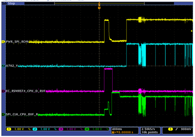
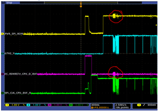
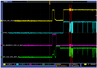
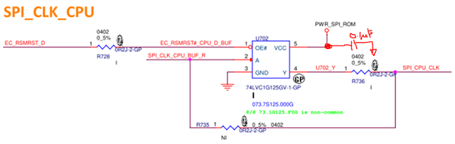
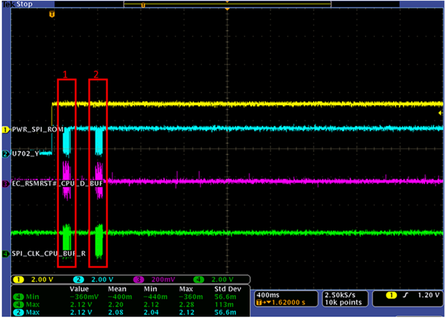
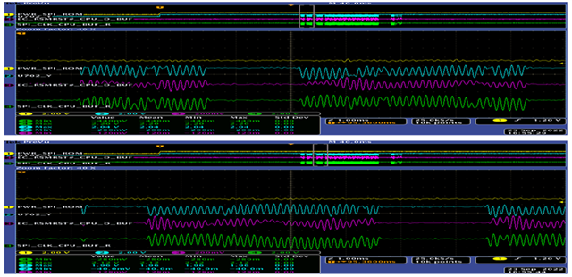
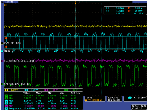
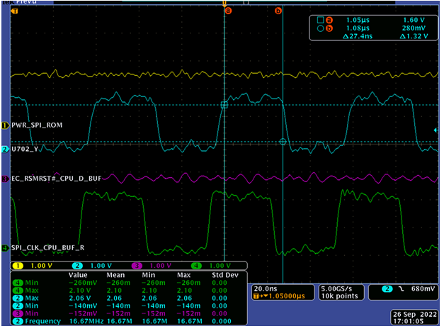
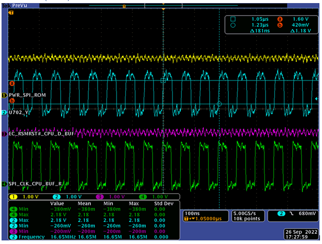
my customer found there's no clock signal when used our buffer,

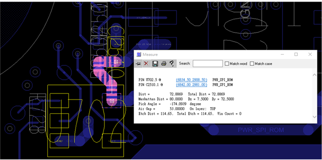
please noted that R735 is DY (the one below).

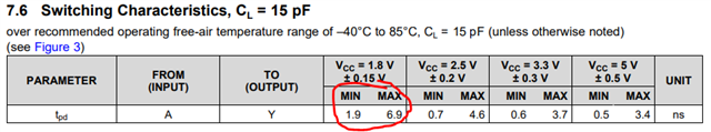
all signal level is 1.8V .

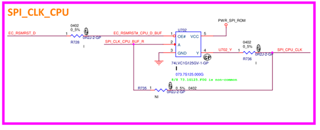
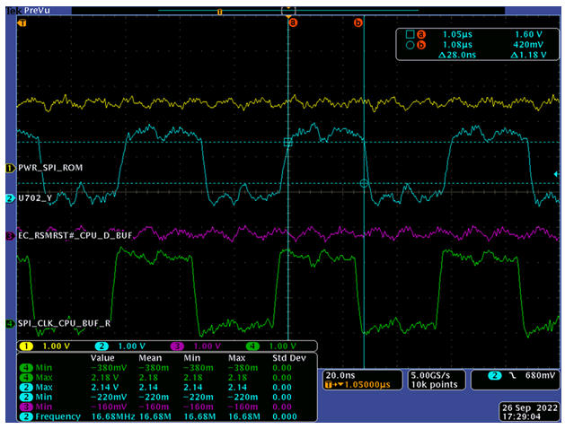
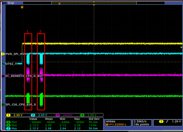
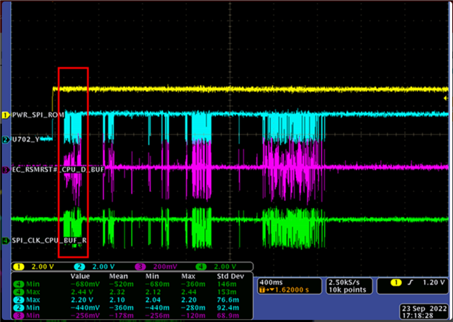
as you can see the blue and green are input and output , and they don't behave like a clock signal,

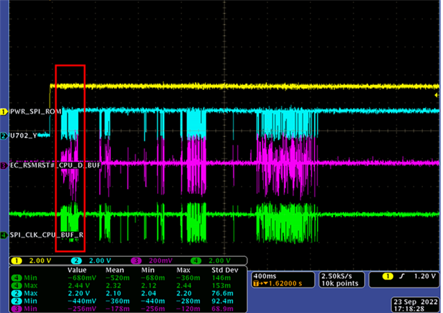
and they said the input signal is behaving normal without our buffer, also Nexperia p2p 74LVC1G125 doesn't have this problem.

please help check, thanks

  • Hi Fred,

    It looks like there's quite a bit of noise on the ground:

    I would recommend to add a good decoupling capacitor near the device. If they have one already, this system may need additional decoupling.

    From this level of view - the input and output appear to be fairly similar. Can we get a scope shot comparing the TI device vs the Nexperia device zoomed in to show the actual clock data rate (appears to be less than 1ms period, but time scale is 400ms per division). Specifically, I'd like to get a good scope shot of this area, but zoomed in to a much smaller scale (preferably 100ns/div or less - but larger scale can be used if it's needed to capture the waveform):

  • Hi Maier,

    thanks

    if the schematic looks ok to you,

    I'll tell them to zoom-in the area and compare with Nexperia,

    BTW, by decoupling , where do you refer to?

  • Hey Fred,

    My apologies - I should have said "bypass" capacitor instead of "decoupling" capacitor.

    Please forgive my poor artwork:

    That should read "0.1 uF"

    Placing a bypass capacitor on the supply pins of a logic device should be standard practice. Here's a detailed explanation of why they are required: [FAQ] How do I select a bypass capacitor for a CMOS logic device? 

  • Hi team,

    sorry , I correct , they use Toshiba TC7SZ125F and doesn't have this problem.

    I understand logic might need decoupling cap but Toshiba doesn't have this issue even without cap,

    maybe it's not the root cause?

    this is ours failed scope

    below is Toshiba pass scope

  • The oscilloscope's sample rate is too low. It must be much higher than the signal frequency to be able to show digital waveforms correctly.

  • Hi Ladisch,

    which graph are you refer to ?

    you mean 2.5Ks/s or 25KS/S?

  • The zoomed-in graphs; they show only curves. Digital signals are square waves.

  • Hi Fred,

    I agree with Clemens on the scope shots - it looks like there's distortion from measurement error here. I'd recommend to trigger on the input signal to the buffer and set the time scale to 100ns/div so we can see better detail of the signals.

    It is likely that they are just pushing the LVC device to it's limits, and the Nexperia device just so happens to have a slightly stronger drive on this batch of parts so it works 'well enough' to not cause issues. I'd recommend to switch to a device that's more optimized for 1.8V operation like the SN74AUC1G125.

  • Hi Emrys,

    I'll tell them to zoom-in more , not just scale but resolution also.

    but about your theory, the toshiba Tpd is actually larger than us, which seems might not match your theory.

    still I'll apply AUC sample to them to give it a shot, thanks

  • You're only looking at the datasheet specs - not the real devices.

    Look at the limits -- 1.9 to 6.9 for us, and 2 to 11 for them. So what if theirs is 2 in this case, and ours is 6.9? Not to mention the fact that t_pd isn't solely related to output drive strength (although there is a correlation).

    I'm not saying I cannot be wrong, but I am saying that you should not discount my advice.

  • Hi Emrys,

    sorry for misunderstanding, I didn't  mean to discount your advice, just want to know more about the reason behind your theory.

    there're not just only one case, according to them , Toshiba passed  all 100 boards.

    back to original , I'm concern is adding decoupling cap at output slowing the whole signal or not?

    since if you suspect the drive is weak in our device in this case, increase the CL might get slower?

    update more zoom-in scope, please help check the difference.

    TI part:

    rise time = 3.866ns ,fall time = 3.2ns

    TOSHIBA part:

    rise time = 3.8ns ,fall time = 2.387ns

  • The decoupling capacitor goes on the supply, not on the output.

    The waveforms of both devices look OK. In fact, I do not see any relevant difference. What exactly do you mean with "no signal"?

  • Hi Ladisch,

    I've already showed this graph above,

    TI: you can see the signal stop switching for a while, seems like there's a error or something cause this. 

    TOSHIBA: However. for toshiba's part, this signal continuously transmitting.

  • A buffer just copies the input to the output. The input signal stays high, so the output stays high. The SN74LVC1G125 works correctly.

    You have to find out why the device that drives the SPI_CLK_CPU_BUF_R signal has stopped. The SN74LVC1G125 (like the Toshiba/Nexperia devices) always has a high-impedance input, so I do not see how it could have any effect on that.

    It might be possible that some bits are not transmitted correctly, but the waveforms above do not show any errors.

  • Hi Ladsich,

    our  part works correctly only at first two communication, we can not be sure there's no timing violation happen after 2sd communication,

    they said the tpd and fall time of our part is larger based on the scope,

    I think our device may operate at its limit, so some will pass some will not.

    let me know your thought?

  • If you suspect that tpd or fall time might be a problem, replace the SN74LVC1G125 with the SN74AUC1G125, which is much faster and stronger at 1.8 V. (And that one certainly needs a properly decoupled supply.)

  • Hi Ladisch,

    seems like this is the only possible cause, the rest are all lure out.

    I'll update after they try AUC version.

    please let me know if you think of other causes, thanks

  • Hey Fred,

    The difference here is less than 1ns for fall time, which is well within our datasheet specification. As Clemens said, this device is operating correctly.

    Adding a bypass capacitor will likely improve the output transition rate and clean up some of the noise seen if they don't have one already.

    This is a standard practice for all CMOS devices and should not be overlooked.

  • Hi team,

    adding up, there's already a 1uF X5R cap close to our VCC pin,

    so the decoupling cap is already there.

  • Hi team,

    AUC part can pass , so issue solved,

    seems like it's delay time problem

  • Thanks Fred,

    Based on the shown noise on their supply lines, I would recommend for them to review and possibly add more bypass capacitors. Please send along this FAQ for details on why multiple capacitors may be necessary:

    [FAQ] How do I select a bypass capacitor for a CMOS logic device?