


Other Parts Discussed in Thread: TXU0202-Q1
Hi,
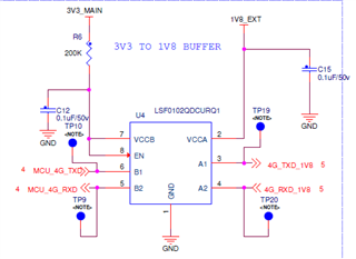
This IC is used as a bidirectional UART. In the schematics shown below, The output A port is 1.8V level and output B is 3.3V.
The issue is the B2 voltage level is 1.8V. What is the issue?
Hi,
This IC is used as a bidirectional UART. In the schematics shown below, The output A port is 1.8V level and output B is 3.3V.
The issue is the B2 voltage level is 1.8V. What is the issue?

