This thread has been locked.

If you have a related question, please click the "Ask a related question" button in the top right corner. The newly created question will be automatically linked to this question.

SN74LVC245A: Guidance to improve the SPI data transmission from MEMS sensor over 2m distance

Part Number: SN74LVC245A
Other Parts Discussed in Thread: DS90LV027, DS90LV017A, SN65LVDT41, DS90LV028A, SN74LVC125A, SN74HCS125, DS90LV012A, TXU0304-Q1, TXU0304, DSLVDS1047, DSLVDS1048, TCA9803, TXB0104, TPD2E009, AM26C32, AM26C31, AM26LV32, AM26LV31, THVD1500, THVD1400, P82B96, DS8921

Dear Community,

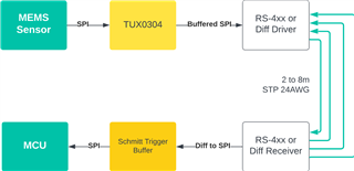
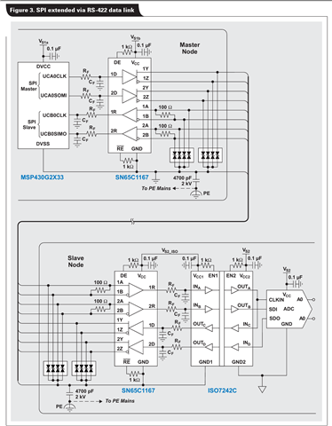
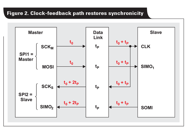
We are currently working on a cost-optimized Condition Monitoring System and are facing a challenge in interfacing our MEMS sensor (IIS3DWB) with the MCU STM32G474 over a distance of 2-4 meters. While we have found multiple buffers and level-translators available for I2C communication, we are unable to locate a suitable solution for our SPI sensor communication over this 2-4 meter distance. We require a robust approach to ensure reliable data transfer from the sensor to the MCU, with a target data rate of up to 150KB/s (or 2MHz clock speeds)

We kindly request your suggestions and expertise in helping us find a suitable solution for this use case. Any guidance or recommended approaches for extending SPI communication over long distances, specifically in relation to our MEMS sensor and the MCU, would be greatly appreciated.

Thank you in advance for your support and insights

  • The average data rate does not matter; what is the SPI clock frequency?

    Just using single-ended signals with buffers (e.g., SN74LVC125A, SN74HCS125) at both ends is possible. But if you expect a noisy environment or a ground shift between the two boards, differential transmission would make sense; there are integrated multi-channel LVDS transceivers like the SN65LVDT41/14, but you could just as well use multiple smaller transmitters/receivers like the DS90LV017A/DS90LV027/DS90LV012A/DS90LV028A.

  • Hello Clemens,
    Thanks for your quick response. LVDS surely seems like the perfect solution for our application, however per channel cost is beyond our budget for this project. Are there any cost-optimized LVDS solutions available?

    The clock frequency we plan for our use case is 1MHz & 2MHz.

    Said that, for a typical industrial use case with CAT-5 high-quality shielded twisted cable, and a maximum distance of 2m, can we do equally well with 2x Level Shifters like TXU0304-Q1, that will convert the MEMS's 3.3V SPI to 5V over the cables & back to 3.3V at the MCU?

    Do suggest us some way to evaluate these two options.

  • Why the TXU0304-Q1? Do you require automotive qualification?

    Transmitting logic signals over S/FTP cables is certainly possible. But the twisted pairs are intended for differential signals; if you transmit two separate signals over a pair, they will interfere with each other. If possible, use paired lines for the same signal, or pair signals with VCC/ground.

    The TXU0304-Q1 certainly works for SPI. I do not know how noisy your environment is; you probably will have to test it.

  • I made that selection as it is Automotive Qualified, based on an assumption the -Q1 ICs will be more robust overall for a small delta in cost.

    Yes, your suggestions for cables have been noted, thank you!

    Any ideas for lower-cost optimized LVDS devices? Also any benchmarks/articles/application notes for signal integrity tests done by TI for SPI transmissions over longer cable distances? I feel this might be a very common use case for customers to extend SPI over 1-2m distance in Industrial environments, as often sensors & the MCU board are far apart.

  • Can we optimize the design such that, we use LVDS DS90LV011ATMFX & DS90LV012ATMFX for MOSI & MISO lines, while we use buffer for CLK & SS lines? Am I missing something major while making this assumption? If this configuration works, we may get to optimize the cost significantly.

  • -Q1 devices might have a wider temperature range (not for the TXU0304), but the main difference is testing.

    Regarding noise, the clock line would be the most sensitive one.

    The cheapest four-channel LVDS devices are the DSLVDS1047/DSLVDS1048.

  • Hello Clemens,

    Thank you for suggesting the low-cost Quad channel LVDS option, which is well-aligned with our project budget.

    Considering that our SPI clock is only 10MHz, I believe this LVDS solution will adequately meet our requirements for high data integrity.

    I have an additional question: If we plan to use level translators like auto-directional TXB0104 for our GPIO inputs on the MCU, as well as for the TXU0304 for another short-distance SPI connection, or TCA9803 for I2C, would this be a suitable approach?

    My intention is moving forward to always incorporate a buffer and level translator for any off-board SPI/I2C/USART communication within a 1.5-meter distance non-noisy environment. Does this approach align with recommended practices? My objective is to leverage the Schmitt trigger & the level translation to improve the noise performance in offboard short (<1.5m) distance applications at the lowest cost (wrt to LVDS). Am I missing something fundamental when thinking in this direction? Kindly guide us.

    Thank you for your insights.

    Regards

  • The TXB has many restrictions. I would not recommend it except when the signals actually are bidirectional, and no direction signal exists. And then you have to ensure that your circuit respects its limitations.

    Using higher voltages reduces noise sensitivity (this is the idea behind RS-232), but not by a large amount. Very noisy environments require differential transmission.

  • Noted.

    Are there some benchmark studies/simulations available that can help us understand the improvement that 5V I2C has over 3.3V I2C signal? 

    Thank you for introducing me to LVDS for SPI & sharing the low-cost LVDS ICs, I shall be using these moving forward for our noisy environment applications.

    Is there any special consideration to be given for LVDS implementation? ESD & other protection measures?

  • Are there some benchmark studies/simulations available that can help us understand the improvement that 5V I2C has over 3.3V I2C signal?

    I don't think you'd need to go so far to understand the improvement in noise margin between these two options.

    Single-ended 5-V signals typically have VIH = 3.5V, VIL = 1.5V, so noise margin of 1.5V in both cases.

    Single-ended 3.3-V signals typically have VIH = 2V and VIL = 0.8V, or a noise margin of 1.3V in the high state and 0.8V in the low state.

    For differential signals, usually noise margin is described differently. Common-mode noise (ie environmental noise that impacts both conductors equally) will be naturally eliminated just by the use of a differential transceiver. Any noise that makes it into a single line could still cause issues, but the differential signal nature generally provides double the noise margin of a single-ended solution of the same voltage.

    Is there any special consideration to be given for LVDS implementation? ESD & other protection measures?

    Any connection that provide a direct conductive path from the outside world into a circuit should have system-level ESD protection added for the best reliability. I would expect something like the TPD2E009 to be a good solution to protect an LVDS port without impacting signal integrity.

  • Hello Emrys,

    As for robust system design, would you suggest us some prominent protection measures (except Isolation which is costly & at times not required) for I2C, SPI, and USART buses?

    So far we have planned to use Poly switches for over-current protection, TVS diodes, and Ferrite beads, do guide us with any additional protection measures that we should aim for system-level robustness. Also if there are some integrated ICs for these rather than installing multiple passive components on the board.

  • As for robust system design, would you suggest us some prominent protection measures (except Isolation which is costly & at times not required) for I2C, SPI, and USART buses?

    I'm afraid that's not really my area of expertise. I can tell you that most ICs aren't designed with system-level ESD protection in mind -- usually they are only built to handle minor strikes during manufacturing (2kV HBM). Anything that's exposed to contact with people or equipment should have an IEC-61000-4-2 rating. There's an app note that covers more details here: https://www.ti.com/lit/sg/sszb130d/sszb130d.pdf 

  • Hello Emrys and Clemens,

    As we conclude this discussion, I would like to provide a concise reference for anyone seeking to extend SPI over 2-3m distances in noisy industrial environments. Could you please share the key parameters to consider when selecting LVDS drivers, as well as any special considerations to keep in mind when using LVDS for SPI over longer distances?

    - Propagation delay
    - Slew rate
    - Output Voltage Swing
    - Common Mode Voltage
    - Input Threshold Voltage

    What additional pointers to look for that can directly impact the SPI signal integrity &/or maximum speeds?

    Thank you for your valuable input, I am now much more confident about using SPI-based Sensors & MCU communication over our requirement use case.

  • In practice, you have to care only that the LVDS driver supports the required data rate, and that its supply or I/O voltage matches your logic voltage. (When large common-mode voltage differences are expected, you'd typically use RS-422/485 instead of LVDS.)

  • Hello Clemens,

    Can you also suggest the use of RS-422/485 IC for similar application? Can we also use RS-485/422 drivers for transmitting SPI Signals?

  • RS-4xx devices are more power hungry and, in general, more expensive.

    When using many channels, see, e.g., the AM26C31/AM26C32 or AM26LV31/AM26LV32; for the back channel, use any 1+1 transceiver like the THVD1500 or THVD1400.

  • Hello Clemens,

    Can you suggest a reference design that will guide us to evaluate the use of RS-4xx for our SPI transmission over the differential bus?

    This seems more promising as we have RS-4xx drivers available with local suppliers while LVDS we need to source via import.

    Also, in our application the power budget is not an issue, we have a stable power supply available.

  • Is the following assumption a valid use case?

    - I've added Buffers for Level translation & Schmitt trigger for improved noise immunity from potential cable issues.

    - RS-4xx diff drivers can be AM26C31/AM26C32 or AM26LV31/AM26LV32;

    - Can the same be used for I2C with P82B96 in between RS-4xx driver & the I2C Slave/Master

    Kindly guide us in the correct direction.

  • Yes. But SPI usually has the MISO signal in the opposite direction, so it's not as simple as using a single AM26xxx device.

    RS-4xx drivers/receivers (as well as LVDS drivers/receivers) accept and output proper logic signals, so noise or slow edges are not a concern, and you should not need separate buffers. (You would only need level translators, and only if your logic runs at less than 3.3 V.)

    The P82B96 can indeed be used to transport I²C signals differentially. (When using RS-485 transceivers, you need full-duplex ones.)

  • Hello Clemens,

    We want to interface a MEMS-based Sensor to our MCU via SPI, and the following Application Note from TI suggests the use of a configuration as follows:

    Before we implement it, I wish to have your suggestion on suitability and if we are missing anything fundamental in simplex communication from the Sensor to MCU?

    We plan to use 2 x DS8921 on both sides, and this configuration reduces the cost per sensor-SPI-MCU drastically over using 2 x LVDS.

    Regards.

  • That application note has an isolator (which increases propagation delay) and runs at high speed. Without an isolator and running at 10 MHz, clock feedback should not be necessary.

    How many SPI signals, in each direction, do you actually need?

  • Ohh, we have 2 MEMS sensors on 2 separate SPI interfaces on the MCU, each MEMS sensor has 3 & 4 wire configuration for SPI.

    We wish to minimize the number of SPI pins, and I am struggling to evaluate if at all we need SC/CS - Chip Select pin if it is always going to be Data from Sensor > MCU. The cost of the solution & reliability of data transmission is crucial in our use case with a maximum distance of up to 3m with the use of STP cable 24AWG with SPIclock of maximum 10Mhz for the signal transmission.

  • The IIS3DWB datasheet shows in figure 2 that the falling/rising edges of the /CS signals are needed.

    You always need to write the register address. And the 3-wire mode uses a bidirectional line and thus cannot be used with RS-422. So you need to use 4-wire mode.

    Are the sensors on the same board, so that they can share SPI signals?

  • Thank you for the feedback, we have 2 MEMS sensors shall be installed on 2 different PCBs which shall be mounted on different parts of a Machine to be monitored for vibration levels.

    These 2 MEMS sensors shall be interfaced with 2 different SPI masters on the same MCU via separate SPI lines using 4-wires.

    So to confirm before final use, are we missing something, when selecting 1 x AM26C31 (4 Driver Channels) & 1 x AM26C32 (4 Receiver Channels) such that we have:

    Master Output (Drivers)
    - MOSI
    - SCK
    - CS/SS 

    Master Inputs (Receiver)
    - MISO 
    - Interrupt 1
    - Interrupt 2

    This configuration is within our budget & suitable for the board space when compared with DSLVDS047/048 ICs. Also, I often wonder why is there a huge price difference for same IC from TI? For Instance, AM26C31IDR is USD 0.23 while AM26C31IDBR is USD 0.416. Are there any functional differences between these other than apparent package differences?

  • For 3+3 channels, these AM26C3x devices indeed are the most cost effective.

    Prices are set by the Supply & Demand Fairy. Sometimes, she's rather capricious.

  • Hello Clemens,

    One final query on this topic, can we use AM26C32IDR drivers with AM26C32IPWR receivers?

    Is there anything obvious we may be missing here? Can we interface any AM26C31xxx device with any AM26C32xxx device?

  • "D" and "PW" are just packages.

    All drivers and receivers that conform to the RS-422 specification work with each other.

  • Hello ,

    I am seeking your guidance on a specific configuration involving the use of AM26C31/32 Drivers for SPI communication in an industrial environment. Our objective is to interface multiple MEMS sensor slaves with a single MCU master over extended cable distances on a single SPI bus.

    Could you please confirm the validity of the following configurations:

    • Daisy Chain Topology: Connecting the slaves in a sequential manner, with proper termination at both ends, adhering to the EIA-422 standard.
    • Star Topology: Connecting the slaves in a star configuration, if possible within the constraints of the EIA-422 standard.

    Your insights into the compatibility, potential challenges, and best practices for implementing these topologies with AM26C31/32 Drivers would be highly valuable.

    Thank you for your expertise and assistance.

  • Differential buses should have a termination resistor at each end of the cable (but not at the transmitter in a unidirectional RS-422 bus). This implies that a star topology would have more than one resistor, but this load would be too high for the transmitter. In other words, the only topology that works for moderate or high speeds is the daisy-chain topology.