This thread has been locked.

If you have a related question, please click the "Ask a related question" button in the top right corner. The newly created question will be automatically linked to this question.

SN74LVC1G126: Output of SN74LVC1G125 when OE tie to reset signal during power ON

Part Number: SN74LVC1G126
Other Parts Discussed in Thread: TLV7021, TLV803E

Hello

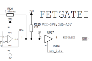
I have a question about the output of 1G126.

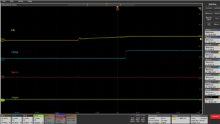
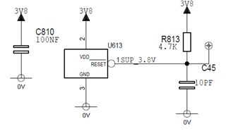
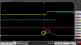
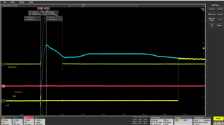
The yellow curve is the power supply of SN74LVC1G126. The blue curve is a reset signal of the power supply and it is connected to OE of the 1G126. The green curve is the output of the buffer.

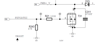
The red curve is the input of 1G126, there is a pulse due to it is the output of a comparator(TLV7021). A pull up resistor connect the output of the comparator to power supply. Due to the POR of the comparator. The output of the comparator is high impedance during power on. As it is pull up to power supply, it is a high voltage level. But we do not expect a high voltage level at the output of the buffer due to the OE is low level and the output of the buffer is high impedance. Due to it is pull down with a 47kohm resistor. It should be low level. But we do see a high level at the output of the buffer.

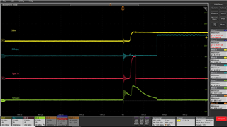
During the test, we found it may linked with the ramp rate of the power supply. If the power supply established in more than 20us, the output is low during power on. But if the power supply established in less than 10us. It has a high level output. I would like to confirm with you about this behavior of 1G126. And could you provide a proper ramp rate for the buffer to work normally.

And if it is not linked to the ramp rate, please tell me why?

Thanks in advance!

  • No pulse seen if the ramp rate of supply is much slower.

  • Hello TI expert

    Would you please support on this topic?

    Thanks in advance!

  • 1. Please show the schematic.

    2. In the first image, there is lots of noise in all for signals. Where does this come from? Can you avoid it?

    3. The green curve does not show a constant high level, but a decaying level, like from an R-C filter. And this happens even before it is powered. So I suspect that the output of the '126 actually is disabled, and that the line is pulled up from somewhere else.

  • Hello Clements

    Please find the schematic

    The noise seen by the oscilloscope may from the probe measurement. I don't think it is the real signal. It is from a capacitor discharge in a fast rate.

    I guess there is pulse at the output of buffer during power on. Then the buffer may change to Hi-Z state, and the voltage in Ciss(MOSFET, BSC059N04LS from Vishay, maybe 2.4~3.2nf) is discharging through R343, 47kohm resistor.

    So my main concern is why there is a pulse at the buffer output during power on, is it from the fast ramp rate of power supply?

    Thanks in advance!

  • Hi,

    What is the input signal? it seems that when the Vcc ramp is fast, the input is still at an in between state which causes the output to be unknown. 

  • The input signal is the red curve. It is the output of TLV7021. Due to the POR of TLV7021, there is a high level during power on. But as the OE of 1G126 is connected to TLV803E reset signal. There is a delay after power on to override the POR of TLV7021.

  • The green signal starts going high when the noise happens, and before the supply actually powers up. As far as I can see, the gate is (partially) powered up, and gets strange signals at all its inputs, so it is plausible that the output is unpredictable in this situation.

    There is no such noise in the second image. Apparently, it is this noise that is causing the problem.

  • Hello Clemens

    I agree the first pulse seen by the oscilloscope is noise which I marked in green. it is probably the measurement problem, not a real signal.

    But the 2nd pulse which I marked in red is really a problem for us.

    Because for the 2nd pulse, the OE is low level. So, the buffer should output a Hi-Z state. But it output a high level during power on. After the output of buffer reach the peak, the buffer seems go into a Hi-Z state. The voltage on the capacitor seems start to decay with the 47kohm resistor.

    But in the second figure, you may not the output of buffer. It seems the buffer stays in Hi-Z state until the blue curve turn into high level.

    So I would say the buffer shortly enter the transparent mode during power on in the 1st figure. We would like to understand why?

    Is it due to the high ramp rate of the power supply? As in the second figure, the ramp rate of supply is much slower than the first figure.

    Thanks in advance!

  • There is no requirement on the supply ramp rate.

    As far as I can see, the buffer is in transparent mode only for a very short time; the output is then in the Hi-Z state, and the gate capacitance is discharging slowly.

    I still think that only the noise makes the circuit behave like this.

  • Hello Clemens

    You are right. The pulse seen from the output of the buffer is not from the buffer. It is probably from the MOSFET

    The buffer is good even the ramp rate of the supply is high.