This thread has been locked.

If you have a related question, please click the "Ask a related question" button in the top right corner. The newly created question will be automatically linked to this question.

CD4093B: Spice model netlist error

Part Number: CD4093B

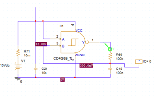
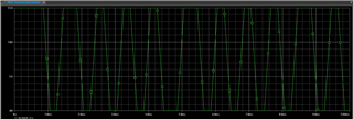
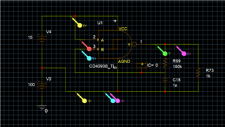
I'm running into a problem with the PSpice model that I downloaded from the product page for the CD4093B.

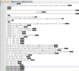
I'll be the first to admit I'm not an expert when it comes to reading model syntax, but it appears to me that the subcircuit "LOGIC_GATE_2PIN_OD_LVC_2i_NAND_PP_ST_CD4093B" has 3 resistors with 1 terminal each tied to GND and the other side of the resistor floating. 

Is there a newer version of the model available, or is there another potential explanation for this issue?

Screenshots included below.

Product Page Link: 
https://www.ti.com/product/CD4093B#design-tools-simulation

Spice Model Download direct link:
https://www.ti.com/lit/zip/schm024

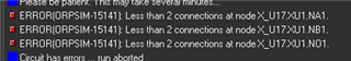
Full error text for future searchability:

ERROR(ORPSIM-15141): Less than 2 connections at node X_U17.XU1.NA1.
ERROR(ORPSIM-15141): Less than 2 connections at node X_U17.XU1.NB1.
ERROR(ORPSIM-15141): Less than 2 connections at node X_U17.XU1.NO1.

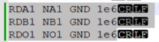
Relevant lines from CD4093.lib:

RDA1 NA1 GND 1e6
RDB1 NB1 GND 1e6
RDO1 NO1 GND 1e6

  • Hi Alex,

    Please give me a day or two to look into this,

    Best,

    Malcolm

  • Thanks Malcolm,

    I'll try to continue making progress using the CD4093B model included with the CD4000 library in PSpice, but that one is a digital model that does not seem to correctly model the supply currents, which are critical in my application. 

  • Hey Alex,

    Are you using the .lib file or the .cir file? I assumed the .lib file based off the screenshot.

    I used the .lib file in TINA and it simulated fine without any errors. Still trying to figure out why you might have gotten the error you did. Could you maybe share your simulation setup with me?

    Best,

    Malcolm

  • Hi Malcolm,

    I was using the .LIB file. Because PSpice has a built in model for the CD4093B it seems to try pulling the built-in model unless I rename the downloaded files from TI. I appended changed the model to CD4093B_TI and re-linked the OrCAD Capture Part to the PSpice .lib file.

    I have created the simplest reproducing case that I could and archived the project.

     4093_Example_Oscillator-2024-02-29T21-21.zip

  • Hi Alex,

    Let me get pspice appropriately configured on my machine and get back to you on Monday with this.

    Best,

    Malcolm

  • Hey Alex,

    Just delete those three resistor nodes in the pspice file and it should work. They aren't connected to anything and don't have any functionality. I guess pspice doesn't like those random floating nodes.

    Best,

    Malcolm

  • Hi Malcolm,

    Were you able to get the simulation to run after deleting those lines? It fixes the netlisting error, but I get several convergence errors pointing to subcircuits inside of the CD4093B model. Given the simplistic nature of the overall example circuit my knee jerk reaction is to blame the CD4093B model for these convergence errors.

  • Hi Alex,

    I'll try to work this on my end when I have time. Have you tried setting initial conditions on the capacitors? These sorts of oscillator circuits pretty commonly run into convergence errors if you don't set initial DC voltages or inject some sort of stimulus to get the oscillation started.

    Best,

    Malcolm

  • Hi Alex,

    Yeah, setting IC = 0V on the capacitor on the output node fixed it. Simulation works for me now.

    Best,

    Malcolm

  • Thanks Malcolm,

    That got me a step closer, but it still seems like I am having model errors when moving over to my actual application. Unfortunately I cannot share the full circuit, so I am simply increasing the complexity of the simplest reproducing case.

    The CD4093B model does not seem to appropriately handle the AGND terminal floating away from the PSpice "0" GND node. I need to utilize the IC in a manner similar to what is shown below, with the AGND terminal being floated to ~100V over my primary GND and the VCC terminal being ~15V above the AGND terminal.

    Adding in the voltage offset from the PSpice GND yields an output that is stuck high and does not oscillate.