This thread has been locked.

If you have a related question, please click the "Ask a related question" button in the top right corner. The newly created question will be automatically linked to this question.

TXS0102: How to TXS0102 decide push pull or open drain?

Part Number: TXS0102
Other Parts Discussed in Thread: TXS0108E, TXS010, OS3

Hi,

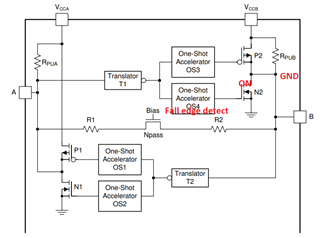
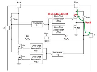
1)  TXS0102 and series can operate both open drain and push pull. But how does it figure out which interface it's driving? When I connect push pull device, push pull drive, when open drain device is connected, open drain drive. How does it decide whether to choose open drain or push pull configurations? I read application notes and watch video series but I couldn't understand why and how it made this choice. 

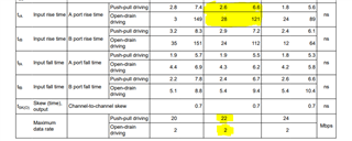
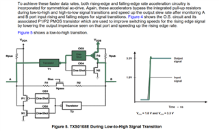
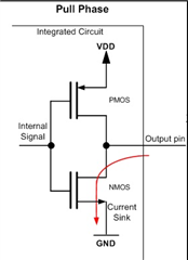
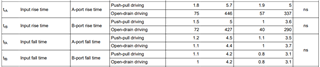
2) I think the push pull structure can be used as an open drain with a pull-up resistor externally, (fix if wrong.) While the supported speed for open drain is 2 Mbps (2V5), for push pull it is 24 Mbps (2V5). While I cannot drive the MDIO interface as open drain, I can drive the MDIO interface when I convert push pull to open drain and use it. Is this approach correct?

3) When used on the MDIO interface, should I calculate the internal pull-up resistor with the external pull-up resistor I will put outside?

  • 1. The TXS accepts both open-drain and push/pull signals from other devices. Its outputs always are open drain. It does not detect the signal type; the only difference is that open-drain signals have slower rising edges, so the maximum speed will be lower.

    2. I do not understand why you would want to change this. Just use the signal as is.

    3. Yes; the external and the two internal pull-up resistors all act in parallel.

  • 1-2) "Output one-shot (O.S.) edge-rate accelerator circuitry to detect and accelerate rising edges on the A or B ports."

    By interpreting this sentence and what you wrote, the push pull structure works when one short circuit that detects rapid rise or fall edges is triggered. When the open drain works, the one shot circuit does not work anyway. That's why the current is pulling through the pull up. If one shot circuit detects, MOSFET use, not pull-up res. Do you support my opinion?

    If this is true, I have to ask a question. According to the table below. (6.10 Switching Characteristics: VCCA = 2.5 V ± 0.2 V)

    If we have 28-121 ns rise time and period 500 ns (2 MHz) signal (max. properties), using open drain.

    If we have 2.6-6.6 ns rise time and period approximately 46 ns (22 MHz) signal (max. properties), using push-pull.

    Please confirm if you support my idea.

    The default MDIO interface is 2.5MHz, but it can be increased up to 12.5 MHz. The interface works as open drain. Then can't I use this IC here? Because it supports 2 MHz (2Mbps) in open drain. But you said I could use it. Can you explain this part?

    3) Should we consider the series resistance in the pass gate transistor line for the TXS0108 in the equivalent resistance calculation? Like 2 parallel resistors in 1 series. This is right?

    Thank you.

  • The edge accelerator works with all signals; most open-drain signals are fast enough to trigger the edge detection.

    For the TXS, there is no fundamental difference between these signal types; the only difference is how fast the edges are.

    The datasheet is misleading; these values are not switching characteristics but timing requirements. When the edges of the input signals are fast enough for the "push-pull" values, then you can do at least 22 Mbps. When the edges of the input signals are fast enough for the "open-drain" values, then you can do at least 2 Mbps. And if they are somewhere in between, the achievable speed is somewhere in between. (I do not know how fast your MDIO edges are.)

    The series resistance has no influence on the speed.

  • Thank you for correcting the misunderstanding in the datasheet section.

    If all signals are running a one shot accelerator, P2 or N2 (P1 or N1) MOSFETs will be turned on depending on the rise or fall edge after a certain point. N2 and P2 mosfets operate independently of open drain or push pull. Then there is no difference between these two ways (push-pull or open drain) of applying. Do you agree with me on this point?

    How does the IC work in terms of push-pull and open drain after one shot accelerator? In fact, the two techniques operate the IC in the same way and the only thing that is different is the rise and fall times?

  • Yes, there is no difference between push/pull or open drain; they are just speed grades.

    For low input voltages, the TXS connects the two pins through the pass gate. For high input voltages, the switch is open, and the pin voltages are determined by the pull-up resistors.

  • Now I'm really confused. Because It is explained differently than what you describe in the TXS0108E datasheet (please look 7.3.1.). A Guide to Voltage Translation With TXS-Type Translators (SCEA044 Application Report) said like this.

    Here, different situations are explained for each accelerator. Also, there does not seem to be a situation where both MOSFETs are turned on.

    I'm curious about your comment.

  • Hello,

    The TXS0108E has two independent One-Shots for both the rising and falling edge, whereas the TXS0102 only has the one. The one shots have their own logic thresholds, once the signal (open drain, or push-pull driver) reaches it, the one shot becomes triggered and lowers the output impedance (essentially shorting the output to VCC/ GND depending on logic high or low) allowing for quicker transition times. 

    After the one shot turns off, the DC state of the logic signal is held high via the internal 10kohm pullup resistor. 

    Here, different situations are explained for each accelerator. Also, there does not seem to be a situation where both MOSFETs are turned on.

    Yes, there wouldn't be a situation for both FETs to be turned on, this would result in large amounts of leakage current with no system benefits. 

    Regards,

    Jack 

  • Hi,

    Thank you for clarifying the opening both MOSFETs.

    When the N2 Mosfet is on in TXS0108E, it pulls current via pull-up. Regardless of whether it is push-pull or open drain. Push phase occurs only when the P2 mosfet is on. In fact, pull phase and open drain should be exactly the same, including speeds, but they are not.

    In the first picture, there is no other possibility of pulling the line to GND. In the second picture, there are two options of setting it to high. The first one is through pull-up, the second one is by turning on the mosfet. In any case, if the accelerator circuit is used, the MOSFET can be turned on and the bus pulled to high. Then no current will be drawn through the resistor. If there is no other possibility, how is there a speed difference?

    There must be a reason why the speeds are different between open drain and push-pull. If mosfets are used in any case, the structure is the same. So what makes it different?

    Can you explain in detail what happens in push phase, pull phase and open drain in TXS0108E? 

  • Hello,

    Push-pull drivers allow faster for faster edges then open-drain since there is no PMOS with open-drain drivers. With open-drain drivers, the initial rise time of the signal is dependent on the internal 10kohms + cap load (RC time constant) until the one shot gets triggered and OS3 becomes activated . 

    Regards,

    Jack 

  • Hi,

    Yes, push-pull is much faster than open drain, I agree. PMOS has nothing to do with open drain, I agree with that.

    But, I don't understand that for open drain drivers, the N2 mosfet turns on and becomes open drain with the Rpub resistor.

    Here is the pull phase for push-pull. 

    However, the integrated circuit already has a parallel resistor at the output. This acts like open drain. I shared a picture in the previous answer.

    The pull phase of push pull in the IC and the open drain were the same? If you say there is no difference, can you explain why there is a difference in speeds? the circuit is the same.

    In summary, the question is, there is already a resistor in the circuit that does open drain. Both in the push phase and the pull phase. However, resistance to the pull phase causes open drain. So why are the speeds different? After all, isn't it the resistance and even the resistance thrown that affects the rise time?

    Could you please explain in some detail?

  • When the TXS detects a rising edge on side A, the PMOS on side B activates for a short time to speed up the rising edge at the output.
    When the TXS detects a falling edge on side A, the NMOS on side B activates for a short time to speed up the falling edge at the output.

    When the other device on side A uses an open-drain output, the input signal arriving at the TXS has a slower rising edge, so there is a longer time before the edge accelerator triggers. But that is the only difference; the output signal of the TXS always has the same speed.

  • Hi,

    The times given in the datasheet describe the times that the accelerator can detect.For example, I shared a picture from the datasheet.

    Actually, there is no different driving, only the slow driven signal is called open drain and the fast driven signal is called push pull. The circuit works the same, the accelerator is triggered at different moments. Is this actually what is meant?

  • Correct.

  • Thank you