


Tool/software:
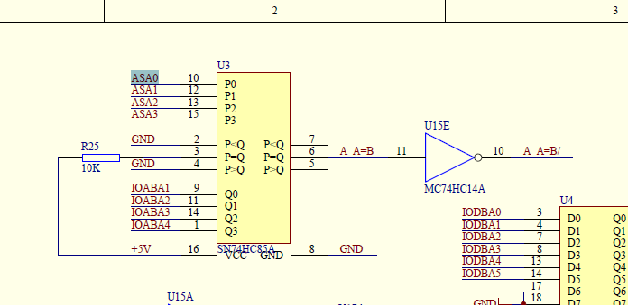
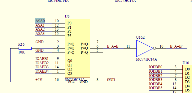
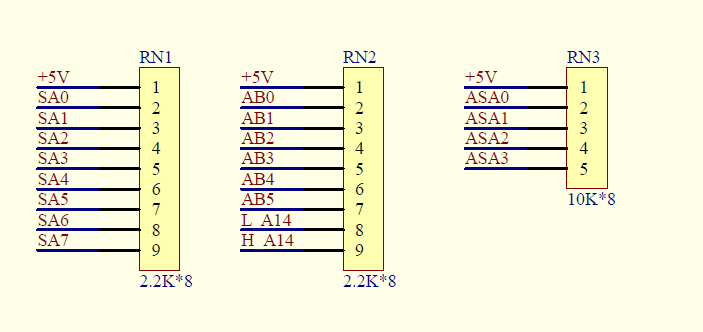
As shown in Figure 3 above, RN3 is connected to the U3 and U9 chips, RN3 is a 10K resistance bar, and U3 and U9 are the chip CD74HC85M. When we measured the electrical rejection impedance at the position of RN3, there were a number of cases where the impedance value was the smallest to 1k, which was directly connected to some pins of materials U3 and U9. We wanted to analyze the reason for the low impedance of RN3, whether it was affected by the design parameters of CD74HC85M?
Some early operations:
1 In batches 1-2, the impedance of the resistance bank was measured directly with a multimeter before the ICT test after the welding was completed, and low impedance was also found.
2 After the normal and abnormal CD74HC85M chips at the RN3 position are removed from the PCB board, the pin impedance connected to the RN3 is measured with a multimeter, which is also different
3. The current treatment method is to directly replace the new materials when there is a deviation in the ICT test, and then test again after the replacement, it can pass the ICT test normally.

