This thread has been locked.

If you have a related question, please click the "Ask a related question" button in the top right corner. The newly created question will be automatically linked to this question.

TPLD1201: logic-Gate with 4 inputs

Part Number: TPLD1201

Tool/software:

Hello all,

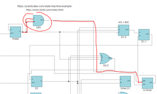
my customer wants to program our TPLD1201. He wants to use a logic gate with 4 inputs. With 4 tomes zero 0000 he wants to achieve on the output 1.

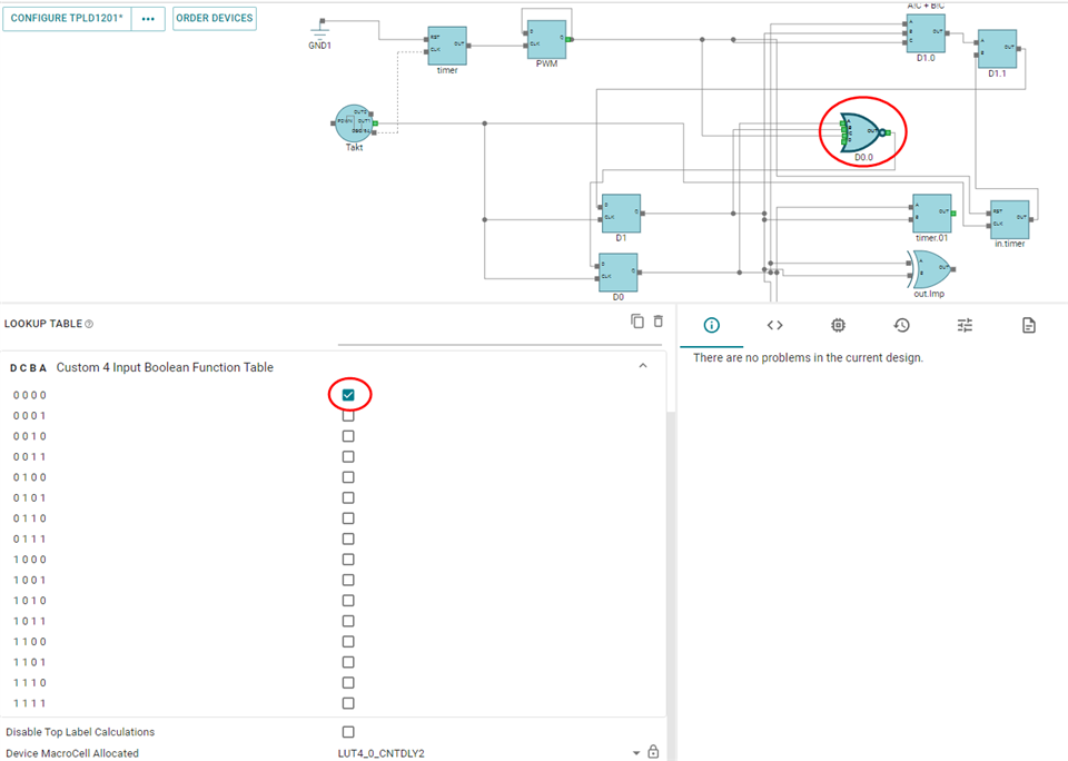
But on the simulation the customer gets a different result:

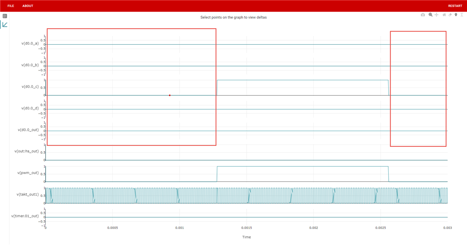
What is the reason for this? Attached the programming file:

statemachine_TI_Anfrage13082024.syscfg

Best regards

Olaf

  • Hi Olaf,

    Thanks for bringing this to my attention I am looking into this now.

    This is highly concerning, and I can give you a  better answer tomorrow.

    -Owen

  • Hi Olaf,

    I investigated your file. This issue is being caused by the RST pin for "in.timer" being connected to both the input and output pins of "PWM". This is causing some sort of feedback loop within the SPICE engine that is breaking everything. You will see if you disconnect the RST pin that the simulation will proceed to work as expected.

    For a quick fix on your end without changing functionality (just for simulation purposes), you can buffer the output of "PWM" with an AND gate as I've shown in the picture below. I have also highlighted the problematic signal path for you. Please let me know if you have any further questions.

    Best,

    Malcolm