


Tool/software:
We are facing a weird issue with one of the Flow meter sensor output signal. Below is the description and I need someone to suggest a solution.
- We have interfaced the flow meter output with our on-board Microcontroller. The flow sensor output is pulsed waveform whose frequency is relative to the flow rate.
- Our microcontroller works on 3V3 logic Voltage and due to this we had to use a Level shifter between the Sensor output and MCU input pin.The sensor output is an open drain, hence we had pulled up the output to 5V using 10K resistor.TP26 is 5V logic input to the Level shifter IC and TP27 is 3V3 logic output of the IC. Please see attached Flow sensor schematic snapshot.
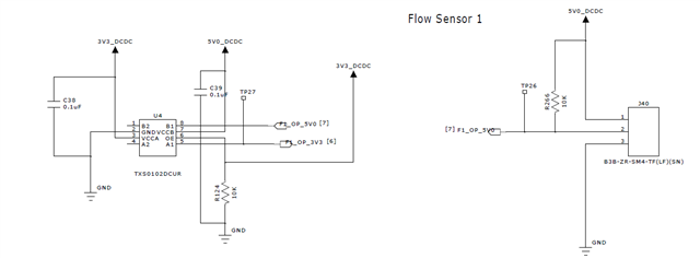
- We are using TI IC TXS0102DUCR Level shifter IC which is generally used for open drain applications.
- Below is the screenshot of the of one of pulse’s Falling edge from the sensor output which is input to the Level shifter IC U4 ( TP 26). Please note that this is when the sensor output is connected to the level translator. When we check the output in isolation from the translator, the below behaviour is not seen.
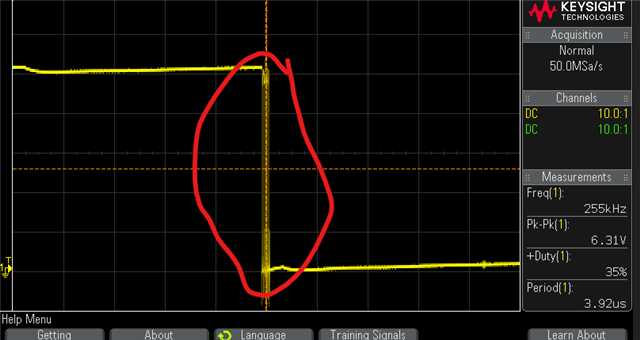
- When we zoomed more on the red indicated area on oscilloscope , we are finding multiple unwanted pulses which lasts for few uS.See below image for reference:

- Because of the above behaviour, our microcontroller is receiving multiple interrupts causing flow rate calculation to be faulty.
- We also tested our Level shifter circuit with a function generator input and found that the circuit works perfectly well.
- We have also checked by removing the external pullup on the 5V rail but this behaviour is still evident.
- When we isolate the output of sensor from the level translator, this behaviour is not there.
We would like to understand what can cause this behaviour? We are able to see the proper pulse train, the only issue while using the level translator is that, at the 5v logic input side itself, these additional jitter is appearing with every falling edge of the pulses.
Regards,
Siddharth

