This thread has been locked.
If you have a related question, please click the "Ask a related question" button in the top right corner. The newly created question will be automatically linked to this question.
Tool/software:
Hi Team,
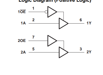
I am trying to simulate SN74LVC2G241 using PSPICE for TI.
there is only .CIR file in TI website. I had converted it to .OLB in generate part tools option.
Refer to the PSPICE error and simulation profile below.
can you share .OLB file for this part?
Kindly guide to resolve this issue.
Thanks,
Vidhya
Hi Vidhya,
I just downloaded and tested the model from TI.com and it appears to work correctly - could you try again and verify there wasn't a mistake in the .olb creation?
Hi Emrys,
can you share the .olb file that has worked for you?
Thanks,
Vidhya
Hi Vidhya,
I didn't use PSpice for TI to verify the model. I just checked that the .cir file is correct using two other simulators - TINA-TI and Qspice. Both worked fine, so I expect the SPICE netlist is correct.
Hi Malcolm,
With the suggested setting, there is still error.
PFA.
Thanks and Regards,
Vidhya
Vidhya,
Could you share a schematic or file of what you are trying to simulate? I doubt this is a problem with our model. It's probably something else in your circuit.
Best,
Malcolm
Just in case, make sure that you have the .lib file for the part added to the simulation configuration. For instructions on how to do that see 2:59 in the following video:
I had used generate part option in PSPICE for TI tool to convert .CIR to .OLB
I see simulation error in PSPICE.
Vidhya,
Did you add the part library to the simulation configuration like the video shows? Could you just send a picture of your schematic?
Best,
Malcolm
HI Malcolm,
PFA schematic. It is not matching datasheet.
Datasheet:
Thanks,
Vidhya
Here is my schematic, which is working fine.
The error here is not with our circuit file. It is something else in your simulation configuration or schematic.
Best,
Malcolm
Hi Malcom,
If you refer to the schematic snap, there are 2 channels. The model shows only one channel and is not matching the datasheet.
Thanks,
Vidhya
Vidhya,
The models are usually made like this intentionally. If you want two channels simply copy and paste the device in the schematic. Each channel has the same behavior.
Best,
Malcolm
Hi Malcolm,
For one channel, the Enable pin is active low and another channel it is active high.
Thanks,
Vidhya
Vidhya,
The easiest solution here is just to invert the input to the enable channel on the one you want to act as active low, or use another model that has active low enable such as the SN74LVC1G125
Best,
Malcolm