Other Parts Discussed in Thread: TXU0204-Q1, , TXS0108E
Tool/software:
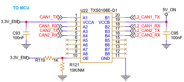
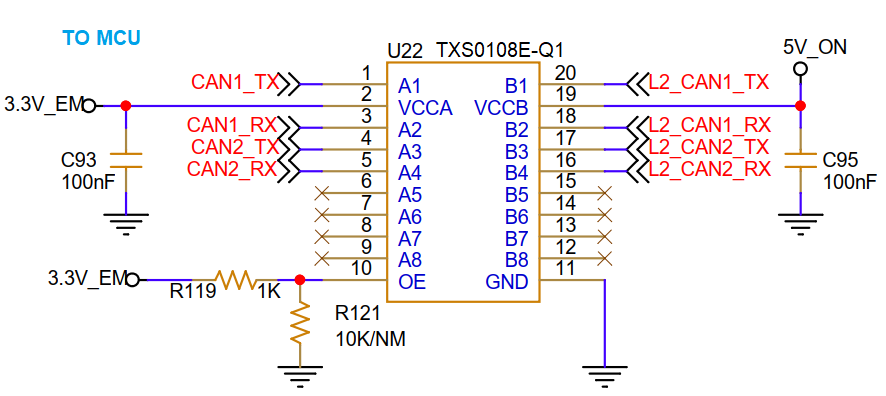
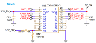
I use the TXS0108EQPWRQ1 in our product for the CAN Transceiver - Microcontroller communication line to act as a level shifter from 3.3V to 5V. The device is a telematics unit designed for Trucks and Buses.
We have received some devices back from the field due to failures in CAN communication, and during our troubleshooting, we discovered that the TXS0108EQPWRQ1 IC was defective, with slight heat being generated on the component.
Simply replacing the TXS0108EQPWRQ1 IC in the affected device resolved the problem. What could be causing this issue, and what steps can I take to prevent it?
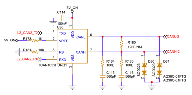
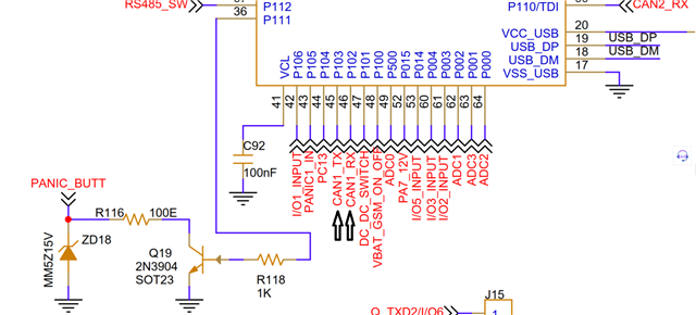
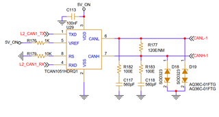
Following is the circuit used
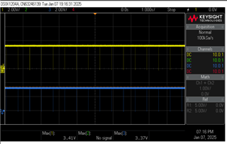
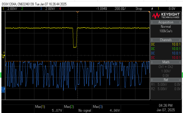
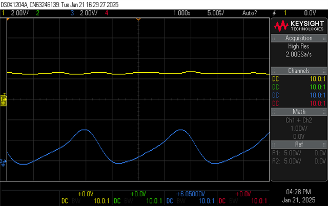
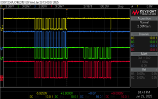
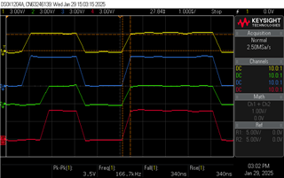
Adding some voltage graph comparison for more insights.
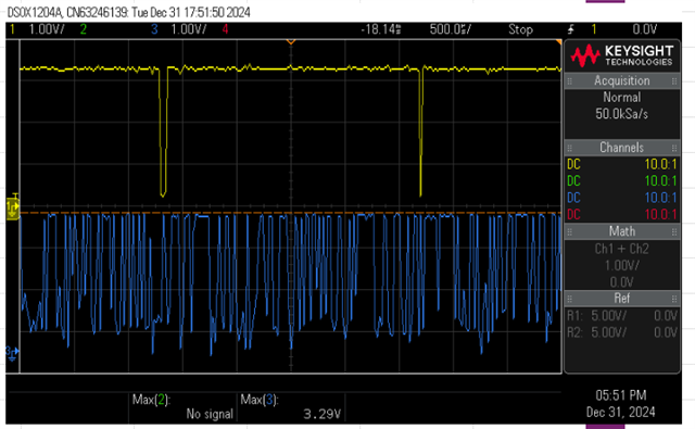
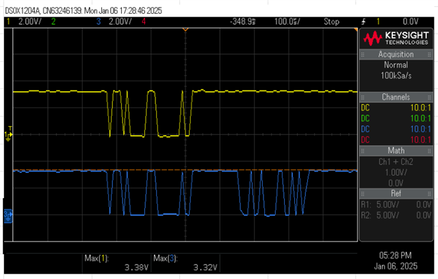
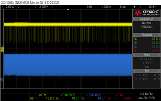
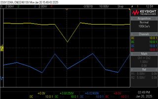
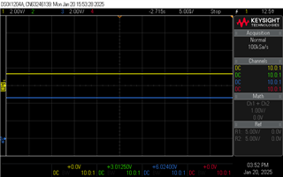
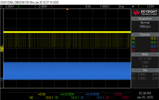
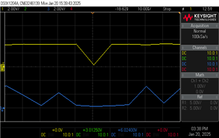
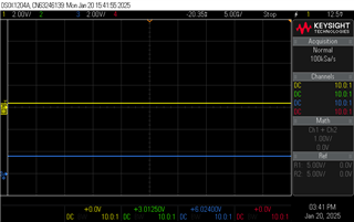
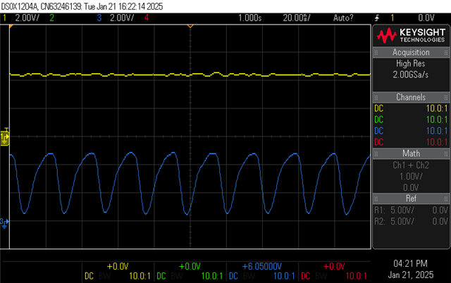
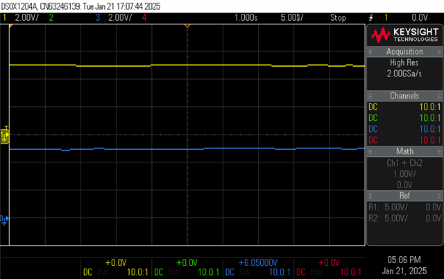
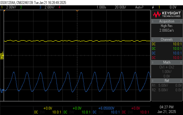
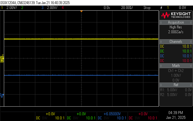
Yellow: TX
Blue: RX
Port-B 5V Graph of CAN1 TX & RX line with NG IC.
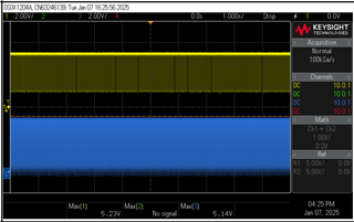
Port-B 5V Graph of CAN1 TX & RX line with Okay IC.
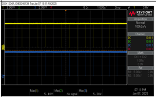
Port-A 3.3V Graph of CAN1 TX & RX line with NG IC.
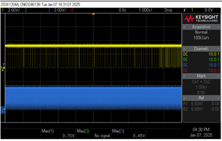
Port-A 3.3V Graph of CAN1 TX & RX line with Okay IC.