This thread has been locked.
If you have a related question, please click the "Ask a related question" button in the top right corner. The newly created question will be automatically linked to this question.
Tool/software:
Dear Support-Team,
Following link which Part i have ordered:
I need for my Boundary Scan test with SFX2 Cube from Goepel Electronic a Signal of 3.3V and also back to my DUT(Device under Test) 5V.
Therefor i tried to use first of all TXB0108, but i got the advice to not use this Component in combination with long cables/Wires etc, rather to use TXB0108 for signals direct on PCBs.
After i found the TXS0108 as another Solution, but with this i can`t get the needed Output Signals.
I also tried to connect OE to GND, but no change.
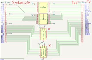
Attached my in use Schematic:
May i ask you for your support , please?
What exactly do you mean with "can't get the signals"? What are the input and output voltages that you expect and that you actually get? Can you show an oscilloscope trace?
In most applications, a buffered translator (TXU0104/TXU0204/TXU0304) would work better.
*Channel A is the 3,3V Side and B the 5V, either if i use the Channel A is Input i dont get 5V as output or the other way around B as Input and don get 3,3V on A as Output.
Oszi trace picture would just show you the same i mentioned already here * -> 0V on the "B1-B8 "Outputs and the 3,3V at the inputs "A1-A8"...
I need a bidirectional Levelshifter, because im sending and reading on both Sides (System and DUT) while Testing.
The TXS is a passive switch and cannot drive the output low by itself.
I suspect that the outputs are disabled. Check the OE and VCC pin voltages.
How can i drive the Output High and low? I need 5V on my Outputs B1-B8 after i have on A1-A8 Inputs the 3,3V.
VCC Voltages A (3,3V) and B(5V) are available, i can measure them.
Have you had a look on my Schematic?
When the OE pin is high (you did not mention this), then the only remaining explanations are solder problems or damaged chips.