Other Parts Discussed in Thread: TXB0108
I'm designing a circuit which employs a couple of TXB0108PWR voltage level translators to interface a 3.3V microcontroller to 5V peripherals. I followed the datasheet and the application note, but somehow I am experiencing some strange results.
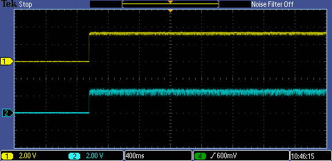
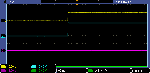
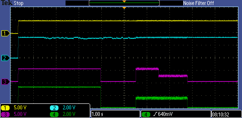
When I apply a 5V DC test signal to the high side of the TXB IC, the low side correctly translates this to 3.3V. However when I remove the 5V signal both the high and low side remain in their high state (5V and 3.3V respectively). When I remove my measurement probe from the high side pin and reapply it, the 5V is gone and the low side goes to zero also. It looks like the pins of the TXB remain clamped until a (minimal) change in impedance (the measurement circuit has 5 Mohm impedance).
When applying a 3.3V DC signal to the low side of the TXB, the high side correctly translates this to 5V. However, when applying 0V again, the high side hoovers around a noisy 2.5V. This only happens when a 3.3V signal has previously been applied, just after power-up the high side is at 0V.

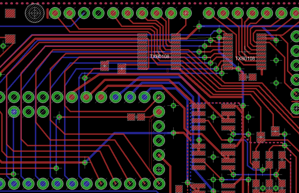
Included is the schematic of how I hooked up the TXB. I'm not using pull-up/down resistors, I'm not driving any (capacitive) loads beside my multimeter or oscilloscope, my inputs can source sufficient current and my trace length is not too long (not more then 2 inches). My power rails are clean and grounding is good.
Any help would be appreciated!