This thread has been locked.

If you have a related question, please click the "Ask a related question" button in the top right corner. The newly created question will be automatically linked to this question.

SN74HC590A not counting

Other Parts Discussed in Thread: SN74HC590A

Hello,

Been a while since I've tinkered around in the digital world so please bare with me. I've searched through multiple channels for info but struck out. Figured I'd finally throw a line out for help.

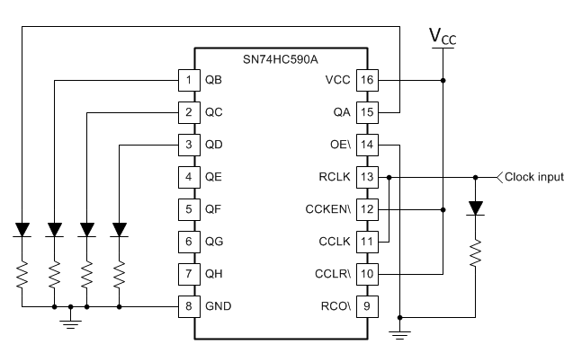
Right now I'm basically trying to get this chip to function on my bread board. Completely isolated from anything else, GRND on pin 8, 5.5V to pins 16,13,12....led's connected to QA, QB, QC, and QD.......and a 5.5V pulse from a on off switch going to the CLK input. None of the led's will light up. I have an led tied into the CLK input and it verifies a good clock signal is reaching the chip. Just not sure what to do. Any help would be appreciated.

Thanks,

  • Hi Brandon,

    My name is Emrys and I will be happy to help you get this working.

    The first rule for any CMOS device is to supply a valid input voltage for _all_ inputs.  Without going into a lot of detail, let's just say that a floating input is bad and can cause problems with your circuit.

    For this application, I would ground the OE\ pin (enables all outputs) -- I drew up a quick schematic so you can compare.  Also you should note that since this device has an output register, if the RCLK and CCLK are tied together, the output will always be 1 count behind the number of pulses submitted to the device.

  • Thanks for your time and help Emrys! I'll get it fired up and go from there.

  • So I just hooked the circuit up as outlined. Had to add ground to OE and add VCC to CCLR. Verified I had a solid 5.5v going into both clock inputs. After multiple pulses, the chip still did not light the diodes. Wondering if I smoked the chip at some point.

    After reading through the 'Implications of Slow or Floating CMOS Inputs', I'm also wondering how well a chip like this will perform in my current application. Here's an overview:

    The output from the NE555P will have a varying frequency between 600Hz  and 1500Hz (controlled by a VR for R2). From the simulator, the out put signals will look like this when R2 is at 1.15M ohms:

    And this when R2 is at 495K ohms:

    The orange wave pattern is the NE555P output and the blue waveform is the output signal at the end of the RC Op amp filter.

    I don't understand / know enough about the sensitivities between various logic inputs to even tell if it will reliably work. All I'm really trying to accomplish is have the output from the NE555P go into some counter. The outputs from the counter will be fed to various AND / NOT gates. The outputs from the AND / NOT gate circuitry will control when the output from the NE555P will be routed to ground through a modest resister......instead of being fed through the RC Op-amp filter.

    Will the SN74HC590A work well in this application or would reliability be questionable due to sensitivities? If I have to switch it up and go with a different type of counter, I'm ok with that too.

    Thanks for your time and help! 

  • 1.15M ohm below

    495K ohm below

  • I would definitely remove the opamp filters -- all they're really doing is slowing down/smoothing the signal and shifting it below zero, which are all bad things in a logic circuit.  In an ideal logic circuit, you will have no voltages below 0, and no voltages above the high voltage (5V in your case).

    It looks like the edges of those signals coming out of the 555 timer are pretty slow - I would recommend adding a Schmitt Trigger buffer prior to the input to the counter to clean that up into a nice square wave.  ST buffers can handle slow inputs by design, and the output will be more than clean enough for the HC590.

    It's likely that the part was damaged if it was connected to that blue signal on any of the inputs (depending on how much current is being sourced from the previous stage) -- this part is only supposed to have inputs from 0 to Vcc.

  • Thanks Emrys. The output from the timer will be fed to the Op amp filter and also the counter. The Op amp filter will need to stay in place because I need a true +/- sine to run an ECU.  

    So, after adding the ST buffers between the timer output and counter input, I should be good then correct? ( After replacing the HC590 chip ).

  • Yes - I believe that will work for you.

    Out of curiosity, what is this being used for?