This thread has been locked.
If you have a related question, please click the "Ask a related question" button in the top right corner. The newly created question will be automatically linked to this question.
Hi Adam,
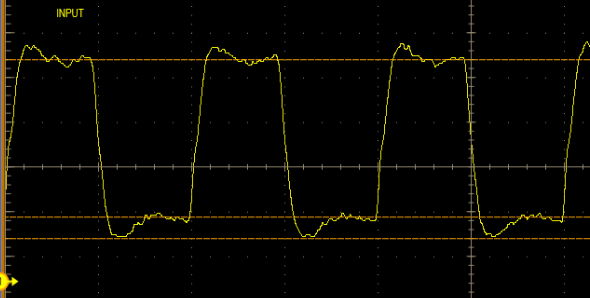
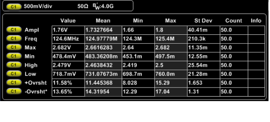
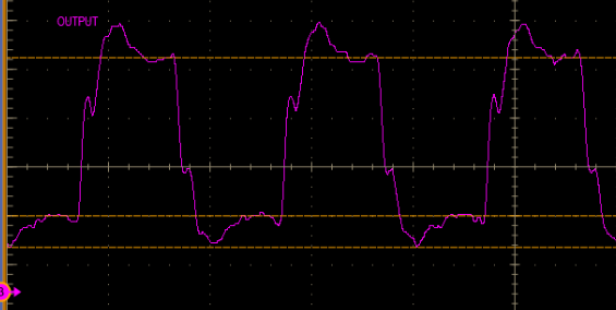
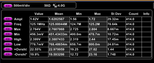
Iam using TS3DV642 as analog switch for RGMII signals. The analog mux is connected to a voltage level translator SN74AVC2T. The 125 MHz RGMII clock signal loses its monotonicity when it reaches the level translator.
Why is this happening between TS3DV642 D2- pin and voltage level translator ?
In the simulation when I put a series termination to this pin, the glitch is removed. Is it because of the impedance mismatch between D2- pin and voltage level translator?
Regards,
Bhavya
Hi,
We have used the voltage level translator for level shifting 125 MHz clock signal as per shown below:
Si53307------------------------------->33 ohm-----------------> TS3DV642-------------------> 0 OHM---------------->SN74AVC2T245
clock buffer analog mux buffer
The input to TS3DV642 (probed at 33 ohm):
The output from TS3DV642 (probed at zero ohm):
Regards,
Bhavya
Bhavya,
Thank you for providing more detail above. This does not look like normal behavior for the TS3DV642 signal switch. We would expect the input of the switch to be the same as the output.
I would like to try and isolate the switch behavior from the system. What happens if you remove the 0 ohm resistor and disconnect the switch from the level shifter? Does the input and output behavior remain the same?
Have you tried removing the TS3DV642 from the PCB and blue wire the signal path? Does this solve the issue? This will help us isolate if the switch is the root cause.
Thank you,
Adam
Hi Adam,
There is no distortion when we give the signal only to TS3DV642 , we have checked that. But when we connect TS3DV642 with level translator SN74AVC2T245 , there is distortion in the signal.So the mux performance is good.
The schematic is as per the block diagram :
We just wanted to know how to solve the issue when the mux is interfaced with level translator.
Regards,
Bhavya
Hi,
Can you please update me on the progress?
We are nearing the end of design phase.
Regards,
Bhavya
Hello Bhavya,
I noticed that you only have a 0 ohm between the mux and the level translator and no coupling capacitors on your diagram. In our application and implementation section of the datasheet, we consistently place coupling capacitors on our mainlink and auxiliary channels. Have you tried populating your circuit with these capacitors?