This thread has been locked.

If you have a related question, please click the "Ask a related question" button in the top right corner. The newly created question will be automatically linked to this question.

CD74HC73: CD74HC73 with SN74121N and DCP010512DBP

Part Number: CD74HC73
Other Parts Discussed in Thread: LM317M, SN74121

Hi,

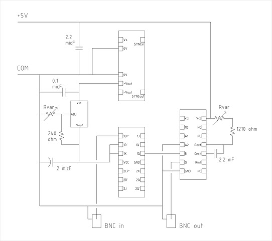
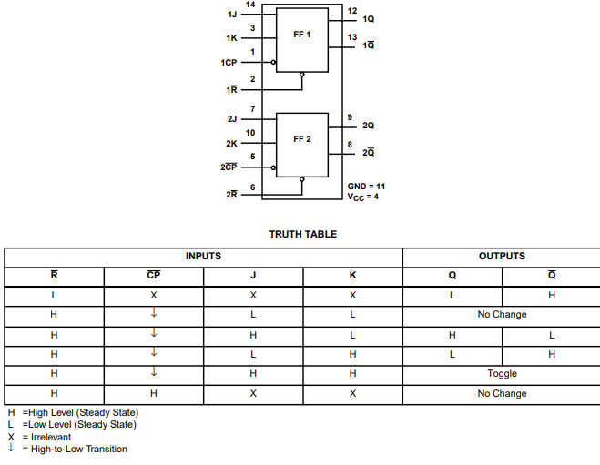
I was passed along the circuit in the attached file. It uses the CD74HC73, SN74121N, DCP010512DBP and LM317M. The purpose of the circuit is to take an input 5V 50kHz signal and output a 25kHz signal with the ability to change the amplitude of the output signal as well as temporally shift the output (via two potentiometers). We have been having some issues with the stability of the circuit over time and would like to be able to either simulate it using spice models OR identify alternative circuit designs/components that can be used to determine if the circuit itself has some inherent issues or it was just some quality issues from our end that caused it to not work as well. 

If someone could review the current design that would be helpful. Any help with identifying other possible solutions to meet our requirements would also be welcome.

Thank youoviyat (1).pdf

  • Hi,

    Can you provide a better schematic? I can't tell which nodes are connected. There are no junction dots. Can you also use the proper symbols for all the parts so I know how they are connected and look at the flow of the parts in the schematic.

    I don't have any spice models for the monostable multivibrator so designing this circuit in a spice software might not be possible. 

    Thanks!

    -Karan

  • This is the best I can do for you. I wasn't the one who designed it so all the "schematics" I have are images I found in our group server. The components aren't labeled as well as the previous schematic but the general position of them is the same in this new one.

  • Hi,

    When you say that the circuit has stability issues, what exactly do you mean? Do you maybe have some scope shots of operations?

    Thanks!

    -Karan

  • Hi,

    Sorry I do not have any scope shots, this was an issue discovered by a remote collaborator on the circuit that we sent them and they didn't collect any data with the scope to send us. Actually disregarding the physical operation of the circuit, is it possible for you to just only find out if the circuit can theoretically perform in the intended manner? If the circuit can work theoretically then the issues we might be having would probably be due to our own construction issues.

  • Hi Kasey,

    This is something you will have to confirm individually between the teams. I can only support the logic parts such as the CD74HC73 and the SN74121. I can see multiple problems with just the schematics of these devices. You have left the inputs floating on these devices which leaves the outputs in an indeterminate state. 

    Both of these parts have a datasheet that contain truth tables that inform what the outputs will be based on the input. For example, 

    As you can see, not knowing what the value on the J pin is, I don't know what the output will be. All CMOS inputs need to be tied to either supply(high) or GND(Low). Another concern is your Supply pin,Vcc, for the JK Flip flop is not connected? In the previous schematic, you had it connected it to the inputs which would not work. You need to connect that to an external supply like you have for the monostable multivibrator.

    I also think you should make separate posts for the DCP010512 and the  LM317. This way the part experts for those devices will give you the best advice.

    Thanks!

    -Karan