This thread has been locked.

If you have a related question, please click the "Ask a related question" button in the top right corner. The newly created question will be automatically linked to this question.

SN74LVC1G373: Logic forum

Part Number: SN74LVC1G373
Other Parts Discussed in Thread: SN74LVC1G14, SN74LS279A, SN74LVC2G132

Hi,

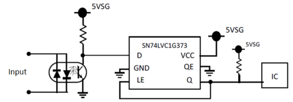
My customer considers the following circuit.


 On this circuit, does this output the following logic waveform, after power-up? Please let me know.


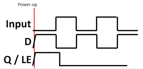
He wants as follows:

When input of D pin moves high to low after power-up, this SN74LVC1G373 outputs high to low on Q pin, and keep low.

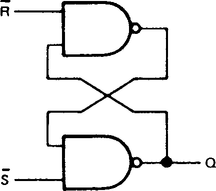
If you have any alternative solution, please advise us.


Thanks and best regards,
M.HATTORI.


  • Hello,

    The circuit above would work, if you could guarantee that the Q output would start driving a high.

    For clocked devices, there is no guarantee that the output will drive one way or another (see https://www.ti.com/lit/an/scha005a/scha005a.pdf).

    So, on power-up, if the SN74LVC1G373 drives a low on Q, this would mean the device would never be enabled to see if D is driven high/low. To fix this, additional external circuitry would be required.

    Please don't hesitate to reach back out if you have any other questions.

    Thanks!

    Chad Crosby

  • The Q/LE signal already has a pull-up resistor, so the simplest way to force it initially high is to add a R-C circuit to OE to enable the output only a short time after powering up.

  • Follow up post:

    To echo Clemens's post: Yes, a simple RC circuit would make this circuit work. However, the OE pin is an active low input and would require an inverter in between the RC and OE pin. You might consider using the SN74LVC1G14 to do this.

    Thanks!

    Chad Crosby

  • C to VCC and R to GND would not need an inverter.

  • An alternative solution would be to use a set/reset latch. Integrated devices like the SN74LS279A are available only in a quad package, but you could construct one from two NAND gates (e.g., SN74LVC2G132):

    S R latch

    Use an R-C circuit to generate a low pulse on S on power-up to initialize it to the high state, and connect the optocoupler to R.

    Functionality-wise, there is not much difference to the SN74LVC1G373 circuit, but the SN74LVC2G132 has Schmitt-trigger inputs.