This thread has been locked.

If you have a related question, please click the "Ask a related question" button in the top right corner. The newly created question will be automatically linked to this question.

CD4046B: Widen Usable PLL Range

Part Number: CD4046B
Other Parts Discussed in Thread: CD4022B

I am using CD4046B with octal counter cd4022b to to 44.1kHz-48kHz and ideally output locked x8 range. So far, best I can get is about 44.1kHz to 46kHz.

Can someone suggest changed values to widen usable input range for f_base?

Details:

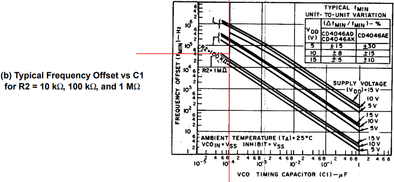
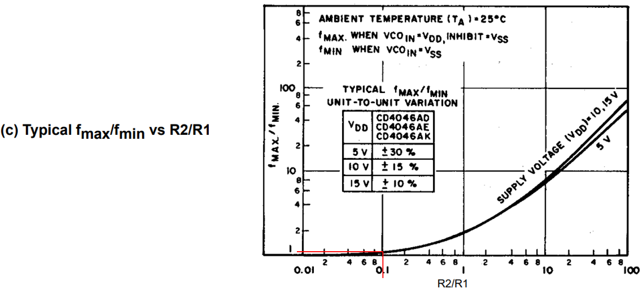
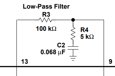
 I have the values as follows: C1=100pf (minimum allowed value) R1=20kOhms R2=100kOhms, R3=4.7kOhms C2=100pf. My goal here is to have a x8 output from the input (f_base) with an f_base of 44.1kHz-48kHz. My current selection of components allows me to have a range from about 43.9kHz-46kHz. Is there some way that I can widen the range a bit to extend it up to a little past 48kHz (just to give it some headroom for swings in f_base)?

Counter IC:

www.ti.com/.../cd4022b.pdf

PLL IC:

ticsc.service-now.com/sys_attachment.do

Thanks

  • Hi Brian,

    This app note is pretty helpful: https://www.ti.com/lit/an/scha002a/scha002a.pdf 

    It sounds like you're looking to expand your frequency lock range (f_max - f_min = 2*f_L) while maintaining your offset (keeping f_MIN constant).

    We can use the provided equations to get the expected component values (note that f_O is the same as f_C -- I think this is a transcription error):

    We already know R2 and C1 to get the desired f_MIN from your existing setup. We can verify with the plot in figure 9b (100 pF, 44.1 kHz, 100 kohm):

    It looks like you're getting a bit less offset than what would be expected from the plot (the middle group of lines is for 100 kohm).  The datasheet & app note think you should be getting around 100kHz of offset for those values, so you might try increasing R2 a bit -- you might be pushing the limits of the offset range for the R2 + C1 combo.

    After that, we need to just take the ratio of f_max and f_min to get the R2 / R1 ratio from figure 9C to calculate R1 (48 kHz / 44.1 kHz = 1.088):

    I had to guess at 1.088 since it's so small and we're on a log scale. Assuming I'm close to right, R2 / R1 = 0.1, and R1 = 10*R2, so R1 = 1 Mohm.

    Basically you're getting close to the limits of the device -- you'll want to use the maximum value of R1 (1 Mohm), you're already at the minimum value of C1 (100 pF) and you can tinker with R2 a bit to try to get your offset exactly the way you want it.

    I don't know if it will be possible for you to get exactly the range you want.

  • Hi Emrys,

    Thank you for the reply. This is helpful.

    One thing I think maybe was not obvious is that I am looking to get 352kHz-384kHz output because I'm using an octal counter. This would correspond to ~44kHz-46kHz f_base (frequency signal input) and then go to the divide by N counter between VCO OUT and COMPARATOR IN (PIN 3&4).

    Are you saying that I should be choosing the components for the input frequency or the x8 Frequency from the Octal counter?

    Do I need to pay attention to the values of R3 and C2 in the filter loop to tune the input frequency range? I'm using Phase Comparator II, and the datasheet says Fc=FL for PC2, but I imagine that it must make some kind of difference. Or should that just be a short? (between PC2 out and VCO IN)

    Thanks

  • Hey Brian,

    Sorry about that - my mistake. I did overlook the counter, even though you stated it clearly... I just got focused on the numbers :)

    That explains why your frequency (44kHz) didn't hit any of the lines in figure 9b -- 350 kHz works better.

    I still think you just need to increase R1 a bit. If that doesn't do the trick by itself, you might try reducing R2 a little bit to drop the offset frequency & change R1 to the max value (1 Mohm) to see how much range you can get out of it.

    For R3 and C2, mostly you just need to pick your loop filter components to have a corner frequency ~2 orders of magnitude less than your VCO frequency. You want it to respond relatively quickly, but also minimize ripple, and I find that to be a good place to be.

    At 350 kHz, I'd go with maybe 0.001uF and 47 kohm, which would give you a corner freq around 3.39 kHz.

  • Thanks for the reply Emrys.

    I got a lot closer. I used the Frequency Synthesizer example from the datasheet you sent me, and that's getting the frequency great, but it's a little jittery. Maybe that mean the LPF components are too "fast?"

    I tried your recommendation, and it was actually a lot more jittery. (47kohms/ 0.001uf)

    I think I need this kind of filter loop with the extra resistor, but maybe a little slower. This is what I did:

  • Some applications work better with an active loop filter -- you can get a really fast response and huge amounts of attenuation. I'm afraid that's a bit outside my area of expertise though.

  • Thanks for the idea. I think though an active filter would probably create too much noise and overcomplicate the circuit. I think the circuit I have now is working alright. I'd like to tune the component values a little more though.

    It started working a lot better after I added the extra resistor between C2 and GND.