This thread has been locked.

If you have a related question, please click the "Ask a related question" button in the top right corner. The newly created question will be automatically linked to this question.

Inverting a 1Mhz square wave

Other Parts Discussed in Thread: LMV116, TLV9151, LMH6639, LMV7219, TLV3201, TLV3501, TMUX1219

Hi team,

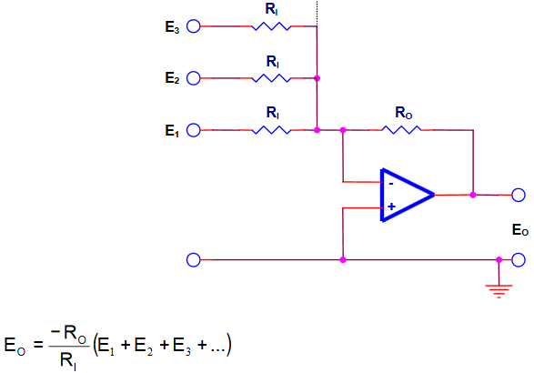
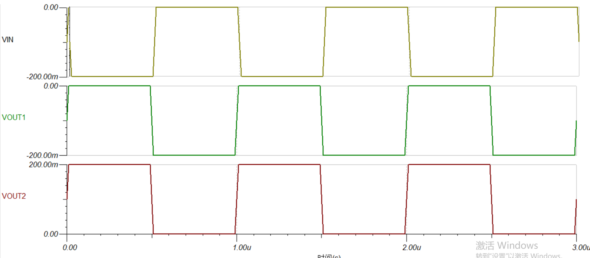
I need to convert a 1Mhz square wave VIN whose VH is 0V and VL is -0.2V to a 1Mhz square wave as VOUT1 or VOUT2 which is shown below. The phrase has to be inverted and the VPP could be VOUT1 or VOUT2.  

1. Do you have any solution according to my issue? The circuit should be as simpler as possible and the cost should be as low as possible.

Best Regards

Wesley Huang

  • These are not logic voltages, so this is not possible with logic devices. However, a comparator, maybe followed by an analog switch, will work.

    Are the +/- 200 mV voltages available as supply or reference voltages? What other supply voltages are available? What is the required drive strength of the outputs? What is the required switching speed of the outputs?

    Should the circuit switch between the two outputs (with what kind of external signal), or is this achieved by modifying the two reference voltages?

  • Hi team,

    1. Supply voltage is 3.3V. But the Vpp of Vout could be any value below 3.3V.

    2. The drive strength is 10mA. The speed is 1Mhz.

    3. Achieving one output is OK. We just need VOUT1 or VOUT2.

    Best Regards

    Wesley Huang


  • VOUT2 can be generated with an inverting amplifier:

    For an amplification of -1, set RI = RO.

    VOUT1 can be generated with a voltage adder to shift the signal by 200 mV:

    Set RI = RO, E1 = input, E2 = 200 mV.

    In both circuits, make the resistors high enough so that the input signal is not loaded too much. If the input signal is too weak, you might have to buffer it with another opamp wired as a voltage follower. This will also be necessary for the 200 mV reference if you generate it with a voltage divider.

    The opamps' slew rate limits the switching speed, so you should choose one with a high value, such as the TLV9151, LMV116, or LMH6639.

    All opamps need a negative power supply.


    If the opamp output is too slow, or if deriving the output voltage from the input voltage is too inaccurate, use a comparator-based circuit. Use a fast comparator (e.g., TLV3201, LMV7219, or TLV3501) to compare the input signal against a -100 mV voltage, and use its output to control an analog switch (e.g., TMUX1219) that switches between the two desired output voltages. This circuit also requires a negative power supply.

  • Former Member
    0 Former Member in reply to Wesley Huang

    Hi Wesley,

    I wanted to add some comments to Clemens’ response to help fill in some details. You can use the circuits suggested by Clemens, but will need to keep some things in mind.

    1. Make sure the common mode voltage of the amplifier you pick includes the V- rail since the input voltage common mode will be GND. Here I am assuming that you will have a single-supply rail. If you use dual supply rails, then this is not so important. Most amplifiers will fall into this category, but it is good to double check.
    2. If your input signal has peaks of only 200mV, then there may not be a big enough voltage difference at the input to put the amplifier into its slew rate region. The switching speed is going to largely be affected by the rise time of the amplifier which depends on the closed loop bandwidth of the circuit. To make this time short, pick a part with a high GBW specification and keep the gain of the circuit low.
    3. If your amplifier is used in a single-supply configuration, the output of the amplifier may show signs of output overload recovery. This means that the output will take extra time to respond and leave the supply rail voltage. The overload recovery time is different for different parts and, if you only go slightly into the rail of the amplifier, the recovery time may not be as bad as the data sheet specification. However, this is another possible delay and you may want to consider this amplifier specification if you use a single-supply.
    4. The settling time of the amplifier will depend on the stability. If your op amp circuit is not very stable, then the settling time will become longer.

    We have more resources on these topics if you need any further help with this.

    Regards,
    Daniel

  • Former Member
    0 Former Member in reply to Wesley Huang

    Hi Wesley,

    I hope all your questions were answered and the issue has been resolved to your satisfaction.  Since, we have not heard back from you in a while, I am going to assume that is the case.

    If you do happen to have any follow up questions, you are more than welcome to post them to this thread and receive further assistance.

    Regards,
    Daniel