This thread has been locked.

If you have a related question, please click the "Ask a related question" button in the top right corner. The newly created question will be automatically linked to this question.

SN74HCS244-Q1: "Convert" digital 3.3V to 5V

Part Number: SN74HCS244-Q1
Other Parts Discussed in Thread: SN7404, SN74LVC8T245, SN74AHCT541, SN74AHCT244

Hi,

In a board that I'm designing, I need to "convert" a 3.3V digital signal into a 5V digital signal. So, I think what I need is a non-buffer that when the input is 3.3V the output is 5V. I research a little, and I found the SN7407DR, that has a VIH = 2V and VOH = Vcc, so I think that works.

But, I found the SN74HCS244-Q1 - it is a Schmitt Trigger input, different from the SN7407DR, which is an open collector, so I think the SN74HCS244-Q1 is better in this way. But, I didnt find on the datasheed his VIH and VOH, so im not sure if it can be used on my project.

Can someone help me? Which one is the best for my purpose? Or should I use another solution?

  • Ops, I mean non-inverting buffer*

  • Hey David,

    I can help you here but I have some questions first i'll need answered to help narrow down the right part for you.
    You've selected an AEC-Q100 device, which means this is more of an automotive part that adheres to certain stress testing conditions. Does the device need to be automotive qualified?
    Also how many channels do you need? SN7404 is a hex while the HCS part is octal. 

    For voltage translation from 3.3V to 5V, have you looked into the voltage translators
    The SN74LVC8T245 may be a good fit

    Thanks,
    Rami

  • This board will be in a ~60°C environment, so I think there is no need to be an automotive part.

    I will need 7 channels, I was planning to use 2 SN7404 on my board.

    I didnt look at voltage translators, thank you, will give it a look. Is there any advantage in using voltage translators instead of the ones that I talk about?

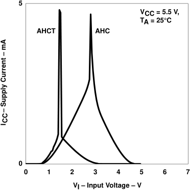
  • If you choose to go with a buffer, this can certainly be done but I'd recommend using a TTL-compatible CMOS buffer. There wouldn't be much difference besides maybe small timing characteristics but nothing so significant that it would be unusable. However, I would avoid using standard CMOS input, since this would result in a high shoot through current if your Vcc is to be 5V and you're input would be 3.3V. Supply current jumps up drastically when your standard CMOS input isn't at Vcc or GND.
    The pros and cons will depend a bit on the device you select and your preference. But you can accomplish what you're setting out to do with either.

  • TTL-compatible CMOS inputs are designed to have practically no shoot-through current for 3.3 V signals:

    For 7 channels, I'd suggest the SN74AHCT244 or SN74AHCT541.

  • Wait, so what the guy say above is incorrect? 

  • Hey David,
    Clemens suggestions are buffers that would work for your use case while the LVC I recommended is a voltage translator.
    With regards to the current spike, we're saying the same thing but I may have made it confusing by omitting a bit of wording. When I mentioned "TTL-Compatible buffers", these are still CMOS inputs; I see I should have worded it as "TTL-compatible CMOS buffers". 
    When I mention CMOS buffers, this is where I should have said "Standard CMOS". 
    I'll edit this above to make it more clear to you and in case anyone in the future may read it.

    Here's more information that may be useful : 
    [FAQ] What's the difference between TTL and 5V CMOS logic?

    Sorry for any confusion,
    Rami