Hi,
I'm currently learning how to program TM4C123x microcontrollers with UART according to the spma074a "Implementation of Programmer for Serial Bootloaders" document. My confusion surrounds the structure of the ACK and NAK packet structures. I have already looked elsewhere in the forum and online for the answer but have come up short. UART settings are baud 115200, transfer size 60 if it matters, using Auto Baud.
I am using only the ROM bootloader, and do not use a custom Flash only bootloader. I am also using the EK-TM4C123GXL evaluation kit, and have a USB connection to the DEBUG USB mini port.
Here are the steps I complete:
- In the LM Flash Programmer application, set interface to ICDI then go to Flash Utilities click Erase to clear entire flash.
- Push the reset button on the evaluation board for good measure
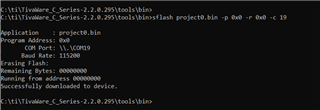
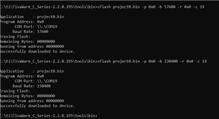
- Flash the microcontroller on the board through UART with a .bin file from a previously compiled project in Code Composer
- Capture the UART packets using a logic analyzer through TX/RX pins on the evaluation board
For Step 3 above, I have tried using:
- LM Flash Programmer with UART (succeeds)
- sflash example program in C:\ti\<TivaWare>\tools\sflash (fails)
In the documentation mentioned above, it says about response packets from the target:
The first type of response packet (Type-1) is an ACK or NAK response, which is generated as a single byte packet when a command packet is sent. The second type of response packet (Type-2) is specific to the GET_STATUS command packet and has the same structure as that of a command packet.
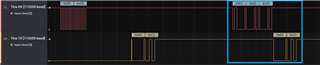
From Step 4 above, with the LM Flash Programmer I am able to see the commands being sent (top) and the responses from the microcontroller (bottom). Clearly seen is the Auto Baud packet 0x55 0x55, a packet from the microcontroller 0x00 0xCC, then the PING command packet (in blue square) and another response from the microcontoller. The responses contain the ACK response (0xCC), however they contain the extra null byte 0x00. This is not documented anywhere and I cannot find out why this is done. And this is all from the ROM bootloader.
With the same steps preceding Step 3 done before trying the sflash example program, the program fails but produces the same output as the LM Flash Programmer:
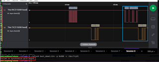
However the sflash program seems to fail to accommodate for the extra null byte, as seen by the error in red. The code shows that it is expecting only the ACK byte 0xCC:
// packet_handler.h
#define COMMAND_ACK 0xcc
// packet_handler.c
int32_t
SendPacket(uint8_t *pui8Data, uint8_t ui8Size, bool bAck)
{
// ...
uint8_t ui8Ack;
// ...
//
// Wait for the acknowledge from the device.
//
do
{
if(UARTReceiveData(&ui8Ack, 1))
{
return(-1);
}
}
while(ui8Ack == 0);
if(ui8Ack != COMMAND_ACK)
{
return(-1);
}
return(0);
}
However, from what I see in the bootloader code, the ACK packet is defined as 0x00 0xCC (bl_packet.c):
//*****************************************************************************
//
// The packet that is sent to acknowledge a received packet.
//
//*****************************************************************************
static const uint8_t g_pui8ACK[2] = { 0, COMMAND_ACK };
Why was the bootloader written this way, and why does the documentation differ? Why is the LM Flash programmer able to accommodate for this difference, and the sflash example program provided by TI is not? What is the reason for the 0x00 null byte?
Thank you,
brandon