This thread has been locked.

If you have a related question, please click the "Ask a related question" button in the top right corner. The newly created question will be automatically linked to this question.

AM2634: MCAL driver with interrupt on Eval Board

Part Number: AM2634

Hello

I try to implement an interrupt on eval board  AM263 CC. The idea is if the button is pushed on the eval board , it should trigger an interrupt. I don't know why, but the interrupt for the gpio pin could not be registered in the interrupt table. 

I could show you my port setup below:

Fullscreen
1
2
3
4
5
6
7
8
9
10
11
12
13
14
15
16
17
18
19
20
21
static CONST( Port_PinConfigType, PORT_PBCFG) PortConfigSet_0_PinConfig[] =
{
{
.Port_PinId = 21,
.Port_PullInhibitEnable = PORT_PIN_PULL_INHIBIT_DEFAULT,
.Port_OutputOverride_Ctrl = 2,
.Port_InputOverride_Ctrl = 2,
.Port_DirectionChangeable = FALSE,
.Port_PinModeChangeable = TRUE,
.Port_PinLevelValue = PORT_PIN_LEVEL_LOW,
.Port_PinDirection = PORT_PIN_IN,
.Port_PinInitialMode = PORT_PIN_MODE_GPIOAB,
.Port_PullTypeSelect = PORT_PIN_PULLTYPE_DEFAULT,
.Port_SlewControl = PORT_PIN_SLEWCONTROL_DEFAULT,
.Port_NumPortModes = 1,
.Port_PinMode =
{ [0] =
{
.mode = PORT_PIN_MODE_GPIOAB,
XXXXXXXXXXXXXXXXXXXXXXXXXXXXXXXXXXXXXXXXXXXXXXXXXX

in main this functions are called:

Fullscreen
1
2
3
4
5
6
7
8
9
10
11
12
13
14
15
16
17
18
19
20
21
Port_Init(PortConfigSet_0_pt);
vimInit();
BswTest_Dio_GPIO21InterruptSetup();
////////////////end main
static void BswTest_Dio_GPIO21InterruptSetup(void)
{
VIMRegs *ptrVIMRegs;
uint32 groupIdx;
uint32 bit;
Vim_IntCfg intCfg;
intCfg.map = VIM_INTTYPE_IRQ;
intCfg.type = VIM_INTTRIGTYPE_LEVEL;
/*
* Register GPIO interrupt
XXXXXXXXXXXXXXXXXXXXXXXXXXXXXXXXXXXXXXXXXXXXXXXXXX

 It is actually a copy paste from mcal library 4.3.1 . Are there some thing wrong?

When the     vimRegisterInterrupt(&intCfg); is executed, the enable bit for interrupt is not set top 1 .!!!

Could you also explain what is for .Port_BankInterruptEnable is the dio config ?

Thank you in advance

  • Hi

    I'm looking into your query, please note that it's a holiday at TI tomorrow so please expect some delay in my response. I should have something my thursday EOD.

    Thanks

  • thank you for your reply. I have an additional question:

    How can I choose the right number of channel Id in the Port_PinConfigType struct? (It would be nice if you can give more information for others entries in the Port_PinConfigType struct elements too)

    Thank you 

  • I also want to ask you how to define this part in code:

    Fullscreen
    1
    2
    3
    4
    5
    6
    7
    8
    9
    10
    11
    12
    13
    14
    VIMRegs *ptrVIMRegs;
    uint32 groupIdx;
    uint32 bit;
    Vim_IntCfg intCfg;
    intCfg.map = VIM_INTTYPE_IRQ;
    intCfg.type = VIM_INTTRIGTYPE_LEVEL;
    /*
    * Register GPIO interrupt
    * */
    intCfg.intNum = 144U;//GPIO_INT_XBAR_GPIO_0_BANK_INTR_1;
    intCfg.handler = BswTest_Dio_GPIO21InterruptHandler;
    intCfg.priority = VIM_PRIORITY_9;
    vimRegisterInterrupt(&intCfg);
    XXXXXXXXXXXXXXXXXXXXXXXXXXXXXXXXXXXXXXXXXXXXXXXXXX
     

  • Hi

    1. Regarding the configuration which you've done, it seems correct and it should work. I'm debugging this on my board too to re-produce the issue.

    2. How can I choose the right number of channel Id in the Port_PinConfigType struct? (It would be nice if you can give more information for others entries in the Port_PinConfigType struct elements too)

    Can you please elaborate on this? I didn't understand the requirement.

    3. Regarding how to define it in the code, you can refer to our example MCAL codes present under the path mcal/examples/Spi -> it has a interrupt configuration done in the example code mibspi_app.c as shown below, Referring to it, the configurations you've done seems to be correct

  • HI Kowshik,

    I did some changes in my code, I think this is more correct than the previous one. But it seems to be still not working. Here are the code snip:

    Fullscreen
    1
    2
    3
    4
    5
    6
    7
    8
    9
    10
    11
    12
    13
    14
    15
    16
    17
    18
    19
    20
    21
    static CONST( Port_PinConfigType, PORT_PBCFG) PortConfigSet_0_PinConfig[] =
    {
    {
    .Port_PinId = 22,
    .Port_PullInhibitEnable = PORT_PIN_PULL_INHIBIT_DEFAULT,
    .Port_OutputOverride_Ctrl = 2,
    .Port_InputOverride_Ctrl = 2,
    .Port_DirectionChangeable = FALSE,
    .Port_PinModeChangeable = TRUE,
    .Port_PinLevelValue = PORT_PIN_LEVEL_LOW,
    .Port_PinDirection = PORT_PIN_OUT,
    .Port_PinInitialMode = PORT_PIN_MODE_GPIOAB,
    .Port_PullTypeSelect = PORT_PIN_PULLTYPE_DEFAULT,
    .Port_SlewControl = PORT_PIN_SLEWCONTROL_DEFAULT,
    .Port_NumPortModes = 1,
    .Port_PinMode =
    { [0] =
    {
    .mode = PORT_PIN_MODE_GPIOAB,
    XXXXXXXXXXXXXXXXXXXXXXXXXXXXXXXXXXXXXXXXXXXXXXXXXX

    The issue in the second question was that, I coudnt understand how the entry number in the cfg sturct is chosen, But I can now relate all the number to the document for sitara 

    Thanks

  • Fullscreen
    1
    2
    3
    4
    5
    6
    7
    8
    9
    10
    11
    12
    13
    14
    VIMRegs *ptrVIMRegs;
    uint32 groupIdx;
    uint32 bit;
    Vim_IntCfg intCfg;
    intCfg.map = VIM_INTTYPE_IRQ;
    intCfg.type = VIM_INTTRIGTYPE_LEVEL;
    /*
    * Register GPIO interrupt
    * */
    intCfg.intNum = 143;
    intCfg.handler = BswTest_Dio_GPIO21InterruptHandler;
    intCfg.priority = VIM_PRIORITY_2;
    vimRegisterInterrupt(&intCfg);
    XXXXXXXXXXXXXXXXXXXXXXXXXXXXXXXXXXXXXXXXXXXXXXXXXX

  • HI Kowshik,

    Do you have any updates?

    Best regards

  • Hi

    Apologies for the delay, I have checked your code, it looks correct...I don't see any reason it's not working properly. I have ran an example on my eval board and I am able to see the interrupt bits being set.

    Can you please tell me what register are you monitoring on the CCS to confirm that the interrupt bit is not being set?

    Thanks

  • Hi Kowshik,

    In the picture below you see the enabled Set is on 0x00004000. It must be 0x00010000, right?

    best regards

  • Is it possible to have your code?

    Best regards

  • Hi

    Can I know why are you seeing VIM registers are variables view? have you written any code to read the VIM Regs and print them?

    However I think that is fine, is it possible we can debug  this over a call? Please let me know your free time and propose a slot so that we can get on live debug session to resolve this. 

    The example code I was testing is the GptApp.c example from the MCAL folder

  • Hi Kowshik,

    I made a global variable for VIM registers. The Gpt example is also running, and the interrupt is registered there. But the example above is related with the interrupt button on the eval board.

    How about on thursday(13.10.2022) for a call? Could yo send me your email? I would send you an teams invitation.


  • Hi,

    I am kind of caught up for the entire week, let's try to have a call next week. However, I have some suggestions for you test before our call (which might solve the issue).

    1. To implement any functionality of the peripherals of our SoC, please refer to the MCU+SDK of that particular SoC, this makes sure that the correct flow is followed, coming to your use case.

    AUTOSAR doesn't usually specify regarding the interrupt for the Dio module (hence that the reason we didn't have the interrupt functionality demonstrated in the example code, however customer can implement it)

    The interrupt on the Dio is little different, the GPIO's on the Am263x are actually grouped into multiple banks i.e., for example 0 to 32 GPIO pins goes into bank 1, 33 to 64 goes to bank 2 etc., and so on.

    So, before you enable the interrupt for the GPIO, it is mandatory to enable the interrupt for the Bank as well, All this information is present in the GPIO_interrupt example of the AM263x MCU+SDK

    you can go ahead and look at the gpio.c file under the source/drivers/gpio path in the MCU+SDK for the implementation of the GPIO_bankIntrEnable

    All these register writes etc., should be added and maintained by you.

    Hope this helps.

    Thanks

  • Hi Kowshik, 

    Could you check this setup on port cfg:

    Fullscreen
    1
    2
    3
    4
    5
    6
    7
    8
    9
    10
    11
    12
    13
    14
    15
    16
    17
    18
    19
    20
    21
    // -------------------- INTERRUPT BUTTON PORT SETUP ----------------------------
    {
    .Port_PinId = PORT_PINID_IRQ_BUTTON,
    .Port_PullInhibitEnable = PORT_PIN_PULL_INHIBIT_DEFAULT,
    .Port_OutputOverride_Ctrl = 1,
    .Port_InputOverride_Ctrl = 1,
    .Port_DirectionChangeable = FALSE,
    .Port_PinModeChangeable = TRUE,
    .Port_PinLevelValue = PORT_PIN_LEVEL_HIGH,
    .Port_PinDirection = PORT_PIN_IN,
    .Port_PinInitialMode = PORT_PIN_MODE_GPIOAB,
    .Port_PullTypeSelect = PORT_PIN_PULLTYPE_DEFAULT,
    .Port_SlewControl = PORT_PIN_SLEWCONTROL_DEFAULT,
    .Port_NumPortModes = 1,
    .Port_PinMode =
    { [0] =
    {
    .mode = PORT_PIN_MODE_GPIOAB,
    XXXXXXXXXXXXXXXXXXXXXXXXXXXXXXXXXXXXXXXXXXXXXXXXXX

    Is this correct?!

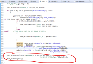
    Within the port init the gpio set direction and mod and bank interrupt enable is already made and I entry into them; look picture below:

    Thank you in advance

  • Hi

    Thanks for checking on this, the port configuration looks perfect. I'll be checking with the expert internally. Also, can you please post the example project which you're trying on your end so that it'll be easy for us to review and check.

    I'll be also evaluating on my board and will come back before Friday EOD. 

    Thanks
    G Kowshik

  • Hi Kowshik

    I can just put some code parts.

    the Port_Cfg setup is shown below:

    Fullscreen
    1
    2
    3
    4
    5
    6
    7
    8
    9
    10
    11
    12
    13
    14
    15
    16
    17
    18
    19
    20
    21
    static CONST( Port_PinConfigType, PORT_PBCFG) PortConfigSet_0_PinConfig[] =
    {
    // -------------------- UART0 RX PORT SETUP ----------------------------
    {
    .Port_PinId = PORT_PINID_UART_RX,
    .Port_PullInhibitEnable = PORT_PIN_PULL_INHIBIT_DEFAULT,
    .Port_OutputOverride_Ctrl = 1,
    .Port_InputOverride_Ctrl = 1,
    .Port_DirectionChangeable = TRUE,
    .Port_PinModeChangeable = TRUE,
    .Port_PinLevelValue = PORT_PIN_LEVEL_HIGH,
    .Port_PinDirection = PORT_PIN_IN,
    .Port_PinInitialMode = PORT_PIN_MODE_LIN0,
    .Port_PullTypeSelect = PORT_PIN_PULLTYPE_DEFAULT,
    .Port_SlewControl = PORT_PIN_SLEWCONTROL_DEFAULT,
    .Port_NumPortModes = 1,
    .Port_PinMode =
    { [0] =
    {
    XXXXXXXXXXXXXXXXXXXXXXXXXXXXXXXXXXXXXXXXXXXXXXXXXX

    call this fuction in main:

    Fullscreen
    1
    2
    3
    4
    5
    6
    7
    8
    9
    10
    11
    12
    13
    14
    15
    Vim_IntCfg GPIOintCfg;
    SOC_xbarSelectGpioIntrXbarInputSource(0x52E02000ul, 14, 145);
    Mcu_Init(&McuModuleConfiguration);
    Port_Init(PortConfigSet_0_pt);
    /* Initialize interrupt */
    vimInit();
    GPIOintCfg.map = VIM_INTTYPE_IRQ;
    GPIOintCfg.type = VIM_INTTRIGTYPE_LEVEL;
    GPIOintCfg.priority = 2;
    GPIOintCfg.handler = &BswTest_Dio_GPIO21InterruptHandler_Test;
    GPIOintCfg.intNum = 142;
    vimRegisterInterrupt(&GPIOintCfg);
    XXXXXXXXXXXXXXXXXXXXXXXXXXXXXXXXXXXXXXXXXXXXXXXXXX

    interrupt function looks like this:

    Fullscreen
    1
    2
    3
    4
    5
    6
    static void BswTest_Dio_GPIO21InterruptHandler_Test(void)
    {
    AppUtils_printf(">>>>Irq for Gpio is working<<<<\n\r");
    }
    XXXXXXXXXXXXXXXXXXXXXXXXXXXXXXXXXXXXXXXXXXXXXXXXXX

    thank you

  • Hi Kowshik, 

    The Problem is solved. The port configuration was a different (see code below).

    Fullscreen
    1
    2
    3
    4
    5
    6
    7
    8
    9
    10
    11
    12
    13
    14
    15
    16
    17
    18
    19
    20
    21
    .Port_PinId = PORT_PINID_IRQ_BUTTON,
    .Port_PullInhibitEnable = PORT_PIN_PULL_INHIBIT_DEFAULT,
    .Port_OutputOverride_Ctrl = 1,
    .Port_InputOverride_Ctrl = 1,
    .Port_DirectionChangeable = FALSE,
    .Port_PinModeChangeable = TRUE,
    .Port_PinLevelValue = PORT_PIN_LEVEL_HIGH,
    .Port_PinDirection = PORT_PIN_IN,
    .Port_PinInitialMode = PORT_PIN_MODE_GPIOAB,
    .Port_PullTypeSelect = PORT_PIN_PULLTYPE_DEFAULT,
    .Port_SlewControl = PORT_PIN_SLEWCONTROL_DEFAULT,
    .Port_NumPortModes = 1,
    .Port_PinMode =
    { [0] =
    {
    .mode = PORT_PIN_MODE_GPIOAB,
    .muxmode = 7,
    },
    XXXXXXXXXXXXXXXXXXXXXXXXXXXXXXXXXXXXXXXXXXXXXXXXXX