This thread has been locked.

If you have a related question, please click the "Ask a related question" button in the top right corner. The newly created question will be automatically linked to this question.

AM2634: Interrupt nesting

Part Number: AM2634

How to enable interrupt nesting in VIM?

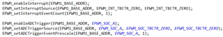
I have two interrupts from Control SS peripherals that I am trying to nest but unable to do so.

I have assigned priorities 2 and 3 to the two interrupts while registering them and i am using a single INTXBAR instance.

  • Hi 

    The interrupts are nested by default. No change is required to be done.

    Also check if the interrupts need to be pulse triggered or level triggered depending on your configuration.

    You can use 2 INTXBARs so that you can configure two unique ISRs that can be nested easily.

    Are you trying this in Free Rtos or No Rtos project?

    The interrupt nesting works like this:

    1. When we get an interrupt, the interrupt is first handled in the Hwip_IRQ_handler, Hwip_IRQ_handler_c. This is where the context saving and register status saving takes place.

    2. When step 1 is happening interrupt nesting is disabled to avoid stack corruption while context saving.

    3. After the step 1 is done, we jump into the Application ISR (the ISR defined by you for that particular interrupt). Before this jump happens we enable Interrupt nesting (basically we enable the hwip to take in any new interrupts if present).

    4. So this is the place where the interrupts are nested.

    Could you tell me how you are testing the nesting?

    We do have an example that we can provide to show interrupt nesting in no rtos.

    Hope this helps.

    Thanks & Regards

    Sri Vidya

  • Hi Sri Vidya,

    Thanks for your response.

    one of my interrupt is pulse triggered and the other level triggered and I am using a No RTOS project.

    I tried using 2 INTXBARs, one of each of the interrupt but I did not see nesting.

    Here is how the interrupts are set up:

    interrupt 1 ==> int num = 146 (from R5FSS0 CORE0 interrupt map), priority = 3, level triggered

    interrupt 2 ==> int num = 147 (from R5FSS0 CORE0 interrupt map), priority = 2, pulse triggered

    to test nesting, I am currently printing A1/B1 when I enter and leave interrupt 1 and A0/B0 for interrupt 2... similar to the interrupt prioritization example from sdk.

  • I have also tried with both the interrupts configured as pulse triggered and it did not work.

  • Hi Sue

    Got it. Thanks for the reply.

    Could you also please respond to the below details:

    Are you able to see the prints on console for both the interrupts? The DebugPLog API which is used to print is disabled inside an ISR.

    interrupt 1 ==> int num = 146 (from R5FSS0 CORE0 interrupt map), priority = 3, level triggered

    May be your Interrupt ISR is being executed quickly before the next high priority interrupt comes?  You can Add GPIO toggle to see the code flow of execution between ISR1 and ISR2.

    About interrupt prioritization:

    The interrupt prioritization example also shows interrupt nesting. Are you able to execute this example in your setup?

    Nesting of interrupts is shown with the help of trace buffer which captures the start and end of each Timer ISR.
    This example configures Timer 0, 1, and 2 interrupt priority in SysCfg with timer 0 priority being highest and timer 2 being lowest and prints a trace for the order of execution. Timer2 is started first followed by Timer1 and then Timer0. Timer2 Interrupts gets nested by Timer1 interrupt which in turn gets nested by Timer0 interrupt.

    interrupt 1 ==> int num = 146 (from R5FSS0 CORE0 interrupt map), priority = 3, level triggered

    About interrupt nesting using EPWM and GPIO toggle:

    What peripherals are you using for setting the interrupts? Is it like EPWM?

    Here is another example for interrupt nesting:

    Below is an example I have done with EPWM interrupts to show interrupt nesting. 

    I Have two EPWM Interrupts as shown below:

    Both the EPWM interrupts are configured for pulse interrupts.

    EPWM 1 ISR priority --> 4

    EPWM 2 ISR priority --> 3

    EPWM1 and EPWM2 have same time period. But EPWM1 counter is started before the EPWM2 So the EPWM1 is always ahead of EPWM2.

    The code flow is below:

    1. First the ISR1 is executed as EPWM1 is always ahead of EPWM2.

    2. EPWM1 ISR has some delay added in the form of FOR loop So the code stays in ISR1.

    3. When EPWM2 ISR is trigger this is pre-empted as it has high priority.

    4. Now EPWM2 ISR finishes execution, then goes back to EPWM1 to finish the ISR execution.

    I am toggling GPIOs in both the ISRs to see this flow:

    Hope this helps

    Regards

    Sri Vidya

  • Hi,


    Yes, I have run Interrupt Prioritization example on my set up and it runs fine and I have used similar method of updating the trace buffer inside the interrupts for printing. I have also added GPIO toggle below to show code flow.


    I am triggering ISR1 from EPWM and ISR2 from ADC and would like ISR2 to be nested inside ISR1.


    Here is the sequence of events:

    At PWM TBCTR = 0

    • ISR1 triggered
    • ADC SOC triggered (I currently have 10 ADC channels set up for conversion using ADC0-ADC4 and SOC0-SOC1)


    AT ADC4 SOC1 EOC

    • ISR2 triggered


    Other settings:

    PWM time base counter = up down mode

    TBPRD = 10000

    TBPHS = 0

    PWM and ADC clock prescaler = 1

    ACQPS = 16


    Below is the GPIO toggle (yellow line - ISR1,  blue line - ISR2).  It seems like ISR2 always executes first because of its higher priority.

    When I give higher priority to ISR1, I see ISR1 executing first and after ISR1 completes execution, ISR2 executes.

  • Hi 

    When I give higher priority to ISR1, I see ISR1 executing first and after ISR1 completes execution, ISR2 executes.

    Yes this is expected.

    Since ISR1 is highest priority, ISR2 is started only when ISR1 execution is completed.

    It seems like ISR2 always executes first because of its higher priority.

    So to check the nesting, your ISR2 needs to be high priority than ISR1. But ISR1 has to start execution first compared to ISR2. I suggest you to Start your ADC SOC at TBCTR > 60 to see that the nesting is visible through GPIOs. I have explained the reason below:

    From the picture you have sent, it looks like ISR2 is indeed nested in ISR1.

    ISR Latency:

    ISR interrupt latency is approximately 415 nsec --> This is the time taken between the ISR trigger and the actual Application ISR execution start.

    ADC Hardware Conversion Latency:

    I see that your ADC start of conversion is also happening at TBCTR = 0.

    ADC Sample Window is 16 Sysclock cycles.

    The core requires approximately 10.5 ADCCLK cycles to process a voltage into a conversion result.

    The ADC End of Conversion --> SOC1 starts after SOC 0 is done. Refer section 7.4.2.6 ADC Conversion Priority in TRM for more information.

    The above two latencies cannot be seen through GPIO toggle. I suggest you to Start your ADC SOC at TBCTR > 60 to see that the nesting is visible through GPIOs.

    Hope this helps

    If it doesn't work, I will also try at my end. Could you also let me know why is the need to nest ISR2 inbetween ISR1?

    Regards

    Sri Vidya