This thread has been locked.
If you have a related question, please click the "Ask a related question" button in the top right corner. The newly created question will be automatically linked to this question.
Hello, my name is Francisco, engineer of the R+D+i Department of the Rother Industries & Technology company.
I would like to ask you if you know a official document where it defines the number and the value of the capacitors that should be located on the 1.2V(VCC: core supply) and on the 3.3V (VCCIO: operating supply for I/Os).
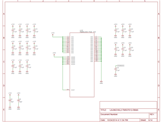
The information I have on this subject is what appears in the schematics of the development kits. In the schematic of the LAUNCHXL2-RM46 appears 11 capacitors of 0.1uF and 1 capacitor of 10 uF for VCC pin (1.2V) and 6 capacitors of 0.01uF and 1 capacitor of 10 uF for VCCIO pin (3.3V), all this referred to the RM46L852CPGET microcontroller. On the other hand, in the schematic of the TMDXRM46HDK, it appears 10 capacitors of 0.1 uF and 1 capacitor of 22 uF for VCC pin (1.2V) and 16 capacitors of 0.01uF and 1 capacitor of 22uF for VCCIO pin (3.3V) , I suppose that all this referred to the RM46L852CZWTT.
In the user guide and datasheet, I can't find any information about this.
Therefore, Could you explain me or send me a official document that details the number and value of the decoupling capacitors for each case?
Best regards,
Francisco
Hi Francisco,
We started working on your issue and we will provide an update soon.
--
Thanks & regards,
Jagadish.
Hi Jagadish,
Thanks for your reply, I look forward to your answer.
Best regards,
Francisco.
Hi Francisco,
herefore, Could you explain me or send me a official document that details the number and value of the decoupling capacitors for each case?
Actually, there is no official document for decoupling capacitors.
I will explain what decoupling capacitors should need to be used,
Hercules devices are fabricated using advanced CMOS technology. The CMOS circuits draw large currents at every transition, producing current spikes on the supply rails. These rising and falling glitches have to be filtered before they traverse into the sensitive circuit area. The bypass or decoupling capacitors placed across power supply pins and ground are used for such filtering.
Hercules devices have several power supply pins. You need to use one capacitor on each power supply pin and should place this capacitor as close to the pin as possible. Typically, small (100nF), low-ESR ceramic capacitors are used for this purpose.
So, please use a 0.1uF decoupling capacitor for each power supply pin irrespective of supply voltage either 3.3 or 1.2v. Like as shown below
For more details you can refer below two threads,
--
Thanks & regards,
Jagadish.
Hi Jagadish,
Thanks for your reply, I understand the reason for using decoupling capacitors and I know that it is due to the use of CMOS technology.
Thanks to you I already understand the reason for placing this number of capacitors since it is due to the number of VCC and VCCIO pins. However, the number of capacitors matches the number of pins on VCCIO, but the number of capacitors does not match the number of pins on VCC. Is it a bug? On the other hand, you have not explained to me the reason for using, apart from these 0.1 uF capacitors, the 10 uF capacitors for the RM46L852CPGET microcontroller and the 22uF capacitors for the RM46L852CZWTT.
Hi Francisco,
Apologies for the delay, it took time to discuss with hardware team and get their feedback as well
owever, the number of capacitors matches the number of pins on VCCIO, but the number of capacitors does not match the number of pins on VCC.
Ignore the number of decoupling capacitors there, but it would be ideal to connect 1 decoupling capacitor to every power supply pin in the controller.
On the other hand, you have not explained to me the reason for using, apart from these 0.1 uF capacitors, the 10 uF capacitors for the RM46L852CPGET microcontroller and the 22uF capacitors for the RM46L852CZWTT.
I discussed this question with hardware team and got below feedback from them.
You can see HDK board is operating with 12v power supply input, whereas launchpad operating with 5v power supply. So their power supply solutions are completely different.
It seems like this may be more of a requirement for the power supply ICs than the device itself. One thing to note; When designing new EVMs, we always perform a Power Distribution analysis where these discrete component values can be fine-tuned to meet system requirements.
--
Thanks & regards,
Jagadish.
Hi Jagadish,
Thanks for your reply. It makes sense that the 10 uF capacitors for the RM46L852CPGET microcontroller and the 22uF capacitors for the RM46L852CZWTT are a specific requirement of some ICs and not of the microcontroller. In any case, I look forward to your team answer.
According to the Power Distribution Analysis, Could you tell me the tools that you use for this analysis?
Best regards,
Francisco.
Hi Francisco,
Sitara Processor Power Distribution Networks: Implementation and Analysis (Rev. F)
This app note contains a lot of details regarding power distribution.
According to the Power Distribution Analysis, Could you tell me the tools that you use for this analysis?
I'm checking with internal hardware team on the exact tool we've used.
--
Thanks & regards,
Jagadish.
Hi Francisco,
Could you tell me the tools that you use for this analysis?
It is SiWave, with Sentinal PSI solver.
—
Thanks & regards,
Jagadish.
Hi Jagadish,
I still cannot close this post since I am still waiting for an answer from your team about the values of the capacitors.
Hi Francisco,
I still cannot close this post since I am still waiting for an answer from your team about the values of the capacitors.
Sorry, what values you are looking for?
Actually, i explained about decoupling capacitors right, and i also explained why we used 10uF in launchpad and 22uF in HDK board right.
--
Thanks & regards,
Jagadish.
Hi Jagadish,
Yes, you explained to me the reasons for these capacitors, but I would like to know, if it is possible, you can explain me what component/s is/are the ones used by these capacitors.
Hi Francisco,
It would be better to follow the design given in launchpad.
1. Use 0.1uF capacitor for decoupling and place the number of decoupling capacitors equal to the number of power supply pins and mount then as close as possible to the power supply pins.
2. Use 10uF capacitor for each supply rail i.e. 1.2v and 3.3v.
--
Thanks & regards,
Jagadish.
Hi Jagadish,
Therefore, the 10uF capacitor were not intended for the ICs but for the RM46L852CPGET microcontroller. Is it finally like that?
Same situation is for the RM46L862CZWT but with the 22uF capacitors?
With this answer I am the same as at the beginning, I still do not know why the 10 uF capacitor and the 22 uF capacitor are used.
Best regards,
Francisco.
Therefore, the 10uF capacitor were not intended for the ICs but for the RM46L852CPGET microcontroller. Is it finally like that?
Same situation is for the RM46L862CZWT but with the 22uF capacitors?
Actually, 10uF can be used for both PGE or ZWT package. As i told before its not specific to the device its more of power supply IC requirements.
Our HDK board designed to operate with 12v power supply with different power IC compared to the launchpad so there we used 22uF. But in general you can follow the launchpad design and you can use the 10uF capacitor.
--
Thanks & regards,
Jagadish.
Hi Jagadish,
I will do what you have told me, that is, I will also put the 10 uF capacitors.
Best regards,
Francisco.