This thread has been locked.

If you have a related question, please click the "Ask a related question" button in the top right corner. The newly created question will be automatically linked to this question.

MSPM0G3107: The measured power consumption of the STANDBY1 mode is greater than 20uA, which is different from the theoretical value of 1.5uA.

Part Number: MSPM0G3107

Hi,

Test the hardware of the motor drive board for us.
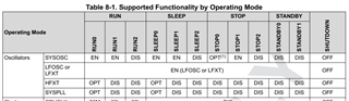
Use the Shutdown mode to measure the current 81uA, and the theoretical power consumption of the SHUTDOWN mode is 50nA, indicating that the peripheral hardware consumption is about 81uA. 
The current measured current is 102uA using the Standby0 mode, indicating that the Standby0 mode is 21uA, which does not declare theoretical power consumption.
The current measured current is also 102uA using the Standby1 mode, indicating that the Standby1 mode is also 21uA, which is far greater than the theoretical value of 1.5uA.
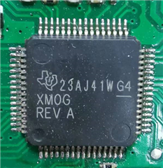
What may be the reason for this? Is it possible that the chip is an old version of the old version. The chip measurement is a sample obtained before December 2022.

 thanks  in advace

  • Hi,

    It is not related to the MCU version. You may need to set all the GPIO pins as output function and output low. And then test the current consumption. 

    Best regards,

    Cash Hao

  • Hi, Cash

    The test data above is based on the configuration of unused pins to pull down input. The test results have not changed when configured unused pins to output low levels.

    Best regards,

  • Hi,

    You have to configure all the pins to output low for current measurement. Otherwise, we do not know whether the current is consume by the MCU or the rest of the board.

    Best regards,

    Cash Hao

  • Hi,

    Thank you for your reply.
    Because the low power mode of the other ics on our board is controlled by some of the pins of the MCU, we cannot configure all the pins to be low. We won't optimize this for now. If we can test the power consumption of MCU separately in the future, we will supplement the test data.

    Best regards,

    Jason

  • Hi Jason,

    Get it. Just to confirm it again, It is not related to the MCU version, we have tested on this pre-release version and the data in the datasheet is from its test results.

    Best regards,

    Cash Hao

  • Hi Cash,

    A board with only MCU system was prepared today, and the sleep current of 1.1uA in STANDBY1 mode was tested when SYSOSC was used as the MCLK clock source. This current is as expected.
    The tests mentioned in this reply are based on all IO ports being configured to output low, including the pins of the SWD interface.
    Now a new problem has been found. After using SYSPLL as the clock source of MCLK, the sleep current in STANDBY1 mode is 48uA, which is expected to be below 2uA.
    The clock configuration code is as follows:

    static const DL_SYSCTL_SYSPLLConfig gSYSPLLConfigSYSOSC = {
    .inputFreq = DL_SYSCTL_SYSPLL_INPUT_FREQ_16_32_MHZ,
    .rDivClk2x = 1,
    .rDivClk1 = 0,
    .rDivClk0 = 0,
    .enableCLK2x = DL_SYSCTL_SYSPLL_CLK2X_ENABLE,
    .enableCLK1 = DL_SYSCTL_SYSPLL_CLK0_DISABLE,
    .enableCLK0 = DL_SYSCTL_SYSPLL_CLK0_DISABLE,
    .sysPLLMCLK = DL_SYSCTL_SYSPLL_MCLK_CLK2X,
    .sysPLLRef = DL_SYSCTL_SYSPLL_REF_SYSOSC,
    .qDiv = 4,
    .pDiv = DL_SYSCTL_SYSPLL_PDIV_2,

    };

    DL_SYSCTL_setSYSOSCFreq(DL_SYSCTL_SYSOSC_FREQ_BASE);

    DL_SYSCTL_configSYSPLL((DL_SYSCTL_SYSPLLConfig *) &gSYSPLLConfigSYSOSC);

    DL_SYSCTL_setMCLKSource(SYSOSC, HSCLK, DL_SYSCTL_HSCLK_SOURCE_SYSPLL);

    DL_SYSCTL_setMCLKDivider(DL_SYSCTL_MCLK_DIVIDER_DISABLE);
    DL_SYSCTL_setULPCLKDivider(DL_SYSCTL_ULPCLK_DIV_2);
    DL_SYSCTL_setPowerPolicySTANDBY1();
    DL_SYSCTL_setBORThreshold(DL_SYSCTL_BOR_THRESHOLD_LEVEL_0);
    DL_SYSCTL_setFlashWaitState(DL_SYSCTL_FLASH_WAIT_STATE_2);

    Best regards,

    Jason

  • Hi,

    The test condition for the STANDBY1 mode should be SYSOSC off. The MCLK should source from LFCLK. 

    Best regards,

    Cash Hao

  • Hi,

    According to the data sheet, both SYSOSC and SYSPLL oscillators are automatically stopped during STANDBY1 sleep, and there is no need to manually switch to LFCLK. The 1.1uA current in the previous reply was also tested with SYSOSC as the MCLK clock source.

    Best regards,

    Jason

  • Hi,

    I tested your code, and find the extra current consumption is coming from the SYSPLL. I do not know the root cause currently, need some time to dig into it.

    Best regards,

    Cash Hao

  • 问题已解决。休眠前将MCLK时钟源切换为SYSOSC,之后设置HSCLKEN.SYSPLLEN寄存器位为0关闭PLL。