This thread has been locked.

If you have a related question, please click the "Ask a related question" button in the top right corner. The newly created question will be automatically linked to this question.

LAUNCHXL2-RM57L: Config the SPI3 to access the AT25080 SPI EEPROM on the Aardvard I2C/SPI activity board

Part Number: LAUNCHXL2-RM57L
Other Parts Discussed in Thread: HALCOGEN, RM57L843

To whom it may concern, 

I am trying to use the SPI3 on the LAUNCHXL2-RM57L to access the AT25080 SPI EEPROM(https://ww1.microchip.com/downloads/en/DeviceDoc/doc3401.pdf) on the Aardvard I2C/SPI activity board. 

The following pins as marked on the board are being used: 

3CS1

3MOSI

3MISO

3CLK

GND

5V

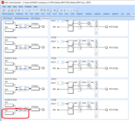
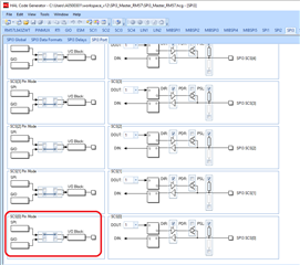
Configured the SPI3 port followed an example here(https://community.element14.com/members-area/personalblogs/b/blog/posts/talk-spi-to-eeprom-with-hercules-launchpad-hero).

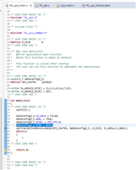
Trying to do a simple application to write and read from the AT25080 as following: 

void Ready_25LC(void) {

  uint16 buffer_status[2]={0x03,0x00};                  // Initial Instruction

  gioSetDirection(spiPORT5, 0x3);

  gioSetBit(spiPORT3, SPI3_CS0, LOW);

  spiTransmitData(spiREG3, &dataconfig1_t, 1, (uint16*) buffer_status);

  spiReceiveData(spiREG3, &dataconfig1_t, 1, (uint16*) buffer_status);

  gioSetBit(spiPORT3, SPI3_CS0, HIGH);

  return; 

}

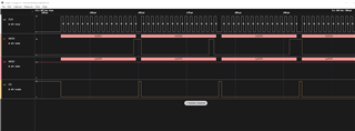
Tried to use a Beagle analyzer to capture the traffic. However, there is not any. The analyzer is working OK since I have used the Aardvark Host adapter and was able to capture the SPI packets. 

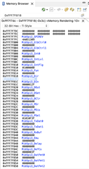
I also tried to dump the spiPORT3 registers since that is what gioSetBit and gioSetDirection is toggling. However, I did not see any MibSpi3_Dir(0xFFF7F818) and MibSpi3Dset or MibSpi3DCLR  change as shown in the memory capture below. Used an meter and measured the 3CS1 pin and did not see any voltage change as well. 

Would appreciate any suggestion from you. 

Thank you,

Helen 

  • Please see the attached project file.

    eeprom_spi.zip

  • Hi Helen,

    I observed one conflict here,

    3CS1

    Here you said you are using 3CS1 right?

    gioSetBit(spiPORT3, SPI3_CS0, LOW);

    But why you are operating 3CS0?

    --

    Thanks & regards,
    Jagadish.

  • Hi Jagadish,

    Thanks for looking into this case!

    Sorry for the confusion. The SPI3_CS0 is defined as 1 in the HL_sys_main.c file. I was experimenting between using CS0 and CS1. 

    #define SPI3_CS0 1

    Regards, 

    Helen

  • Hi Jagadish,

    Still the SPI3 port registers at 0xfff7F800 are not changing after spiInit, which sets the spi3Reg directly. Especially the MibSpi3_GlbCtrl0 and MibSpi3_GlbCtrl1 are still 0 which shows they are not enabled after spiInit which sets these registers directly:

    Memory Browser:

    0xFFF7F800 MibSpi3_GlbCtrl0
    0xFFF7F800 00000000
    0xFFF7F804 MibSpi3_GlbCtrl1
    0xFFF7F804 00000000

    In HL_spi.c: 

    void spiInit(void)

    {

        /** @b initialize @b SPI3 */

        /** bring SPI out of reset */

        spiREG3->GCR0 = 0U;

        spiREG3->GCR0 = 1U;

        /** SPI3 master mode and clock configuration */

        spiREG3->GCR1 = (spiREG3->GCR1 & 0xFFFFFFFCU) | ((uint32)((uint32)1U << 1U)  /* CLOKMOD */

                      | 1U);  /* MASTER */

    ...

        spiREG3->GCR1 = (spiREG3->GCR1 & 0xFEFFFFFFU) | 0x01000000U;

    }

    Appreciate any help since this project is urgent. My project file is attached earlier. Would appreciate if you can double check my GIO, SPI, MIBSPI settings and project setting in general since I am new to Halcogen and CCS. 

    Thank you, 

    Helen

  • BTW, I run another sample project for LED toggling with GIOs and the gioPort register is updating when the gioSetDirection and gioSetBit function are called. So it looks the CCS memory display is behaving correctly. My SPI issue should still be with the SPI configuration. 

  • Hi Helen,

    What do you want to do with CS pin?

    I mean you manually want it to operate as GPIO or you want it to control by SPI hardware automatically?

    Just let me know your requirement, then i will create one demo project for you.

    If you want it to operate as GPIO then you should make sure below things:

    You should configure the pin as GIO in port settings:

    And now call the gioSetBit as follow

    gioSetBit(spiPORT3,0,1); // to SET the CS0 pin

    gioSetBit(spiPORT3,0,0); // to CLEAR the CS0 pin

    --

    Thanks & regards,
    Jagadish.

  • Hi Jagadish, 

    The RM57L843 eval board acts as a SPI master, its CS pin((in this case MIBSPI3 CS1) selects the SPI eeprom slave device, so the CS pin should be a GPIO, correct? 

    Thank you for your help creating a sample project. Note I also want to enable DMA on this SPI access, so if you can show sample code/configuration on that, it would be very much appreciated. 

    Thank you, 

    Helen

  • Hi Helen,

    The RM57L843 eval board acts as a SPI master, its CS pin((in this case MIBSPI3 CS1) selects the SPI eeprom slave device, so the CS pin should be a GPIO, correct?

    No, that is not correct.

    Actually, there are two options to control the CS pin of any SPI device.

    That is manually by configuring it into the GPIO pin.

    or

    It can be automatically operated by SPI hardware.

    In most of the cases people will prefer second method that is controlling automatically by SPI hardware. Because there is no extra overhead in this method, in this method whenever we wrote a frame into the SPI data buffer then the CS pin automatically get activated, after that data will be shifted with the clock, once the all the required data is shifted then CS pin will automatically get deactivated.

    In some rare cases like there is no option to connect the SPI CS pin to the slave device or mistakenly a wrong pin connected with the slave devices, in those cases people will use GPIO as a CS.

    I guess in your case you need to control automatically by SPI hardware.

    I will provide a code for this.

    --

    Thanks & regards,
    Jagadish.

  • Hi Helen,

    Here is the example code for SPI3 Master on RM573

    SPI3_Master_RM57.zip

    In this example i am using the SPI3_CS0 as chip select and i am operating this pin automatically by SPI hardware 

    So i configured the corresponding pin into the SPI mode instead of GIO

    and to activate this pin i am writing 0xFE to the CSNR of the configuration.

    And in this example i am sending 8 frames of data from 1 to 8, and here is the final output on logic analyzer

    In above diagram you can see that CS is automatically operating by SPI hardware between each frames.

    Please take my code as reference and do the necessary modifications on your end.

    --

    Thanks & regards,
    Jagadish.

  • Hi Jagadish, 

    It worked! I just changed the SPI3 CS1 pin, and set the CSNR to 0xFD to match my board settings.

    Thank you very much for the help. 

    Helen